Test B: Warning Indicator On, System Is Not Charging
- Remove and inspect battery junction box fuse No. 2 (30-amp). Inspect Gray fusible links located near battery junction box. Replace fuse and/or fusible links as necessary. If okay, go to next step.
- Measure voltage of Black/Orange wire at generator B+ terminal. If battery voltage is present, go to next step. If battery voltage is not present, repair open in Black/Orange wire between generator and battery. See WIRING DIAGRAMS . Retest system operation.
- Disconnect generator 3-pin connector. Measure voltage of Yellow/White wire at generator connector terminal "A". See Fig 1 or Fig 2
. If battery voltage is present, go to next step. If battery voltage is not present, repair open in Yellow/White wire between generator and battery junction box. See WIRING DIAGRAMS . Retest system operation.
- Start engine. Measure voltage of Light Green/Red wire at generator terminal "I". See Fig 1 or Fig 2
. If battery voltage is present, go to next step. If battery voltage is not present, repair open in Light Green/Red wire between generator and instrument cluster. See WIRING DIAGRAMS .
- Connect generator 3-pin connector. Start engine. With engine running at 2000 RPM, turn headlights and rear defogger on, and turn blower motor to high speed. Measure voltage drop of Black/Orange wire between generator terminal B+ (component side) and battery positive terminal. If voltage drop is less than .5 volts, replace generator. See GENERATOR under REMOVAL & INSTALLATION. If voltage drop is greater than .5 volts, repair high resistance in Black/Orange wire between generator and battery junction box. Retest system operation.
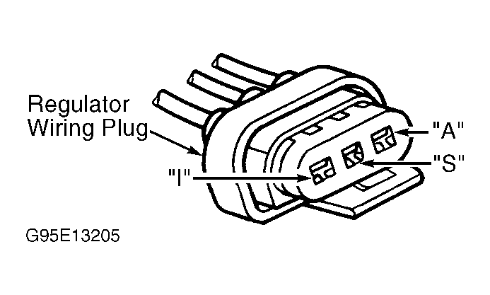 Courtesy of FORD MOTOR CO.
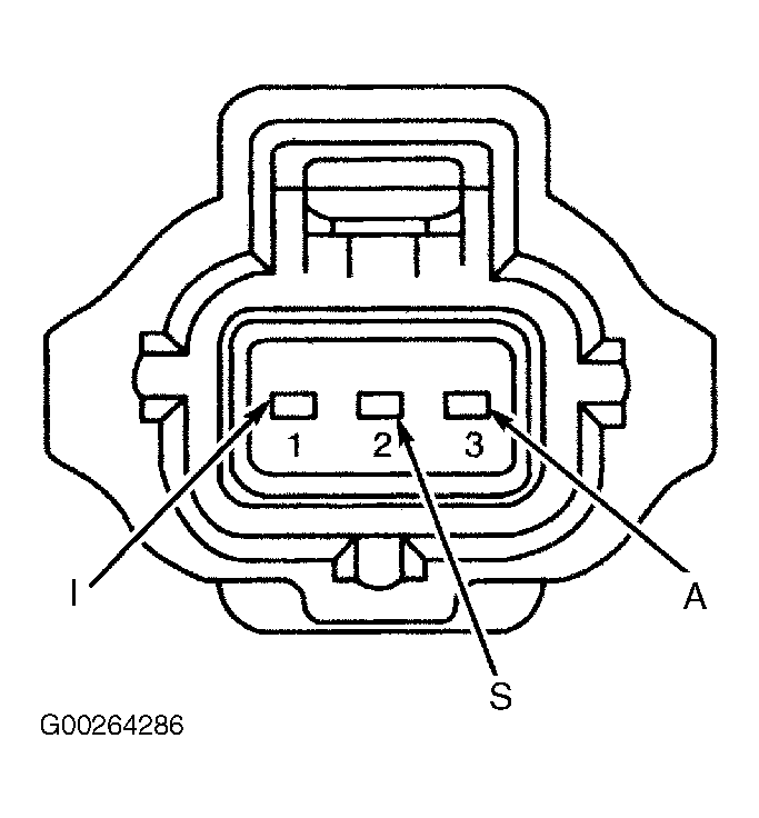 Courtesy of FORD MOTOR CO.