Test A: Both Mirrors Inoperative
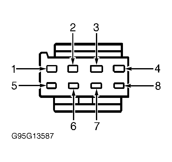
- Remove mirror control switch and disconnect mirror control switch 8-pin harness connector C501. Measure voltage between ground and mirror control switch connector C501 terminal No. 1 (White/Violet wire). See Fig 1
. If more than 10 volts exists, go to next step. If 10 volts or less exists, repair power distribution circuit. See appropriate wiring diagram in
POWER DISTRIBUTION article in WIRING DIAGRAMS.
- Measure resistance between ground and mirror control switch connector C501 terminal No. 5 (Black wire). If resistance is 5 ohms or less, go to next step. If resistance is greater than 5 ohms, repair open in Black wire. Recheck system operation.
- Disconnect passenger's mirror 3-pin harness connector C610. Measure resistance of Yellow wire between passenger's mirror harness connector C610 and mirror control switch harness connector C501 terminal No. 6. If resistance is 5 ohms or less, replace mirror control switch. If resistance is greater than 5 ohms, repair open in Yellow wire. Recheck system operation.
 Courtesy of FORD MOTOR CO.