Test A: Speed Control Inoperative
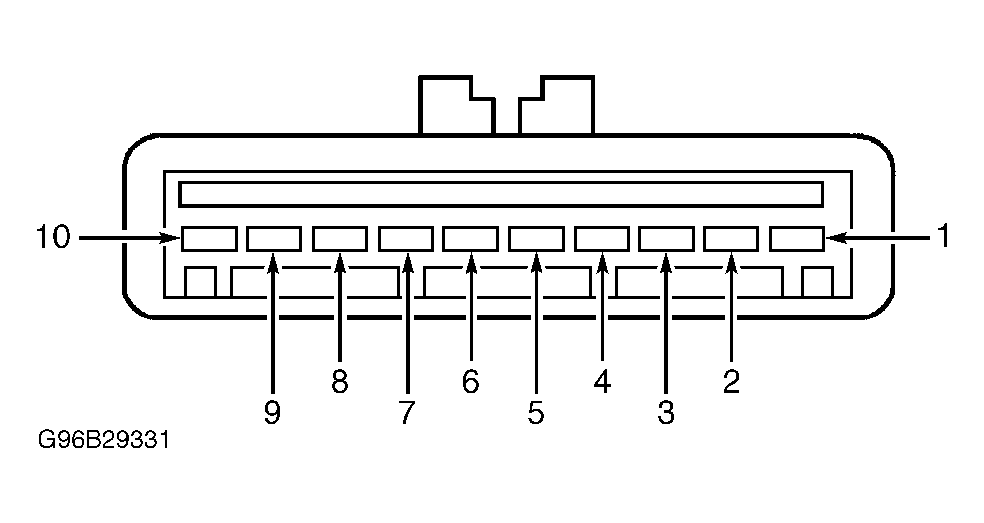
- Turn ignition off. Disconnect speed control servo/actuator connector C146 (located near master cylinder). Turn ignition on. Using a voltmeter, check voltage between servo/actuator connector C146 terminals No. 7 (Violet/Orange wire) and No. 10 (Pink/Orange wire). See Fig 1
. If voltage is 10 volts or less, go to next step. If voltage is more than 10 volts, go to step 3
.
 Courtesy of FORD MOTOR CO.
- Turn ignition off. Using an ohmmeter, check resistance between ground and speed control servo/actuator connector C146 terminal No. 10 (Pink/Orange wire). See Fig 1
. If resistance is less than 5 ohms, repair Violet/Orange wire between instrument panel fuse block and speed control servo/actuator. Retest system operation. If resistance is 5 ohms or more, repair open Pink/Orange wire between speed control servo/actuator and ground. Retest system operation.
- Check stoplight operation while pressing and releasing brake pedal. If stoplights operate properly, repair stoplights as necessary, go to next step. If stoplights do not operate properly, see appropriate wiring diagram in EXTERIOR LIGHTS article to continue diagnosis.
- Turn ignition off. Using an ohmmeter, check resistance between speed control servo/actuator connector C146 terminals No. 4 (Light Green wire) and No. 10 (Pink/Orange wire). See Fig 1
. If resistance is less than 20 ohms, go to next step. If resistance is 20 ohms or more, repair open Light Green wire. Retest system operation.
- Ensure ignition is off. Using a voltmeter, check voltage between speed control servo/actuator connector C146 terminals No. 9 (Red/Light Green wire) and No. 10 (Pink/Orange wire). See Fig 1
. If voltage is 10 volts or less, go to next step. If voltage is more than 10 volts, go to step 8
.
- Ensure ignition is off. Disconnect deactivator switch connector C151 (located on bottom of brake master cylinder). Using an ohmmeter, check resistance between deactivator switch terminals (component side). If resistance is less than 5 ohms, go to next step. If resistance is 5 ohms or more, replace deactivator switch and bleed brake system. Retest system operation.
- Ensure ignition is off. Using a voltmeter, check voltage between ground and deactivator switch connector C151 Light Green/Red wire terminal. If voltage is more than 10 volts, repair open Red/Light Green wire between deactivator switch and speed control servo/actuator. Retest system operation. If voltage is 10 volts or less, repair open Light Green/Red wire between instrument panel fuse block and deactivator switch. Retest system operation.
- Turn ignition on. Using a voltmeter, check voltage between speed control servo/actuator connector C146 terminals No. 5 (Light Blue/Black wire) and No. 10 (Pink/Orange wire). See Fig 1
. If voltage is present, go to next step. If no voltage is present, go to step 11
.
- Disconnect speed control switch connector from steering wheel. Turn ignition on. Using a voltmeter, check voltage between speed control servo/actuator connector C146 terminals No. 5 (Light Blue/Black wire) and No. 10 (Pink/Orange wire). See Fig 1
. If any voltage is present, go to next step. If no voltage is present, replace speed control switch and retest system operation.
- Disconnect air bag sliding contact connector C223 (located on top of steering column, near clockspring assembly). Turn ignition on. Using a voltmeter, check voltage between speed control servo/actuator connector C146 terminals No. 5 (Light Blue/Black wire) and No. 10 (Pink/Orange wire). See Fig 1
. If any voltage is present, repair Light Blue/Black wire. Retest system operation. If no voltage is present, replace air bag sliding contact and retest system operation. See AIR BAG RESTRAINT SYSTEMS - ECONOLINE article.
- Using an ohmmeter, check resistance between speed control servo/actuator connector C146 terminals No. 5 (Light Blue/Black wire) and No. 6 (Dark Green/Orange wire) while pressing speed control SET/ACCEL switch. If resistance is not 612-748 ohms, go to next step. If resistance is 640-720 ohms, go to step 14
.
- Ensure ignition is off. Disconnect air bag sliding contact connector C223 (located on top of steering column, near clockspring assembly). Using an ohmmeter, check resistance in Light Blue/Black wire between speed control servo/actuator connector C146 terminal No. 5 and air bag sliding contact connector C223. If resistance is less than 5 ohms, go to next step. If resistance is 5 ohms or more, repair open in Light Blue/Black wire. Retest system operation.
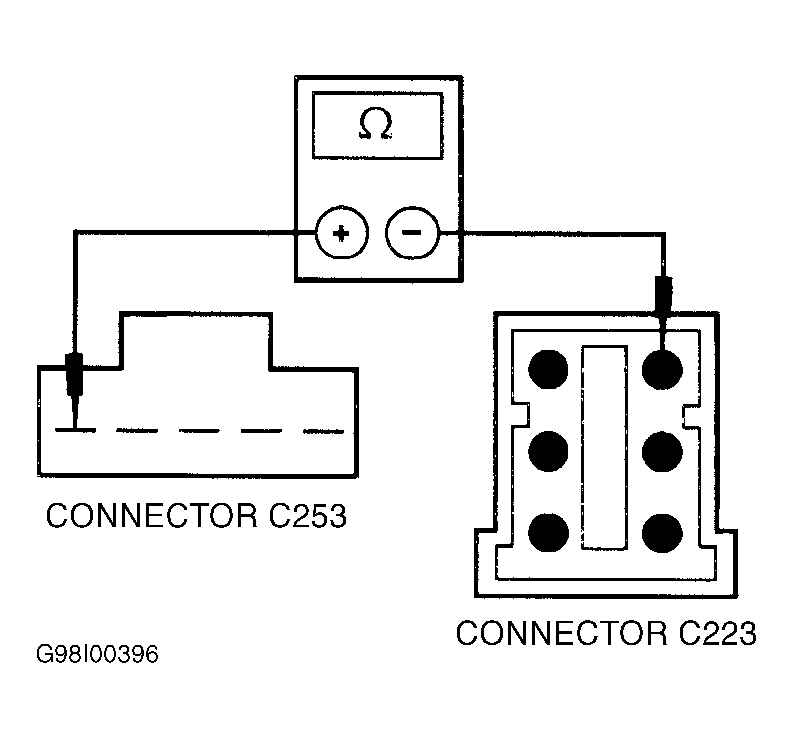
- Remove driver's side air bag. See AIR BAG RESTRAINT SYSTEMS - ECONOLINE article. Using an ohmmeter, check resistance between air bag sliding contact 5-pin male connector C253 terminal No. 1 and air bag sliding contact 6-pin male connector C223 terminal No. 1. See Fig 2
. If resistance is less than one ohm, replace speed control switch and retest system operation. If resistance is one ohm or more, replace air bag sliding contact and retest system operation.
 Courtesy of FORD MOTOR CO.
- Disconnect PCM connector C154 (located in left rear of engine compartment, near brake master cylinder). Using an ohmmeter, check resistance in Gray/Black wire between speed control servo/actuator connector C146 terminal No. 3 and PCM connector C154 (terminal No. 68 on all models except 6.8L; terminal No. 46 on 6.8L). If resistance is less than 5 ohms, go to next step. If resistance is 5 ohms or more, repair open in Gray/Black wire. Retest system operation.
- Ensure ignition is off. Disengage speed control servo/actuator cable from servo/actuator. Inspect cable by pulling end of cable and observing throttle movement. Replace cable if broken or binding and retest system operation. If cable is okay, replace servo/actuator and retest system operation.