Test D: Remote Anti-Theft Personality (Rap) Module Does Not Respond To NGS Tester
- Turn ignition off. Disconnect RAP module 26-pin connector located at left rear corner of cab. Inspect RAP module connector and Data Link Connector (DLC) for physical damage, bent terminals or corrosion. Repair connectors as necessary and retest system for normal operation. If connectors are okay, go to next step.
- Measure resistance of Light Blue/White wire between terminal No. 3 at RAP module connector and terminal No. 7 at DLC. See Figure and Figure. If resistance is less than 5 ohms, replace RAP module and retest system for normal operation. If resistance is 5 ohms or more, go to next step.
- Disconnect and inspect both halves of 84-pin in-line connector C201 located behind left corner of instrument panel. Inspect connector for physical damage, bent terminals or corrosion. Repair connector as necessary and retest system for normal operation. If connector is okay, go to next step.
- Measure resistance of Light Blue/White wire between terminal No. 3 at RAP module connector and terminal No. 51 at male half of in-line connector C201. See Figure and Fig 1. If resistance is less than 5 ohms, repair open in Light Blue/White wire between female half of in-line connector C201 and DLC. Retest system for normal operation. If resistance is 5 ohms or more, repair open in Light Blue/White wire between RAP module connector and male half of in-line connector C201. Retest system for normal operation.
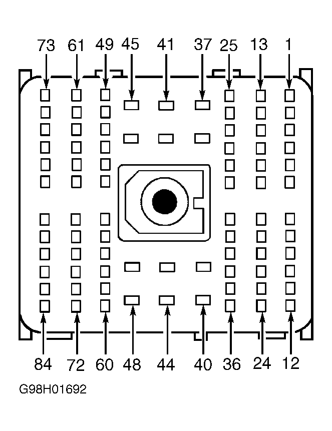 Courtesy of FORD MOTOR CO.