Motor Will Not Run In Any Switch Position
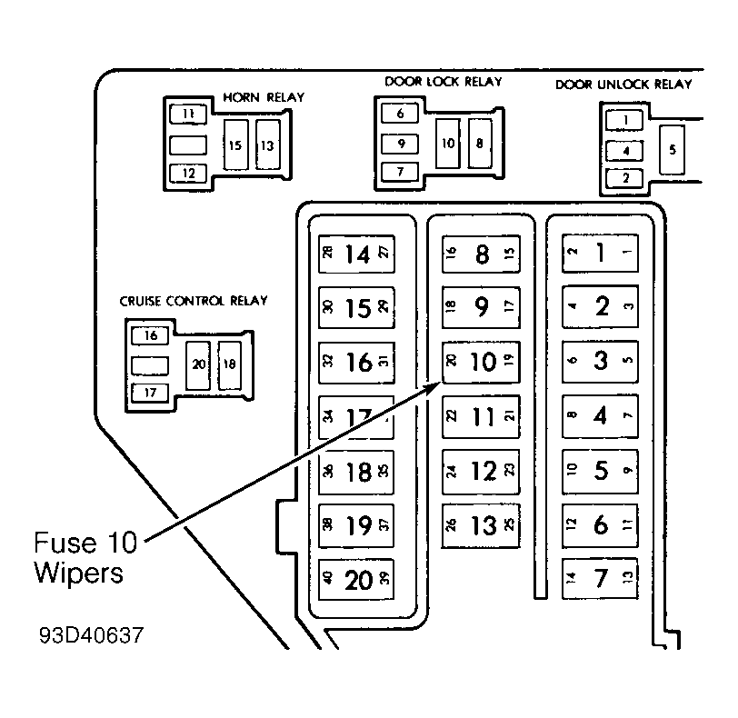
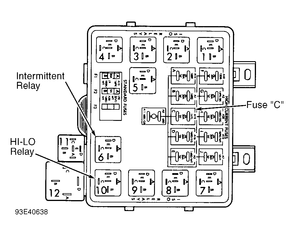
- Check fuse No. 10 in junction block and fuse "C" in power distribution center. See Fig 1
and Fig 2
. If fuse(s) are good, go to step 2). If fuse(s) are defective, replace and check motor operation in all switch positions. If motor is still inoperative, and fuse does not blow, go to step 2). If replacement fuse blows, go to step 10).
 Courtesy of CHRYSLER CORP.
 Courtesy of CHRYSLER CORP.
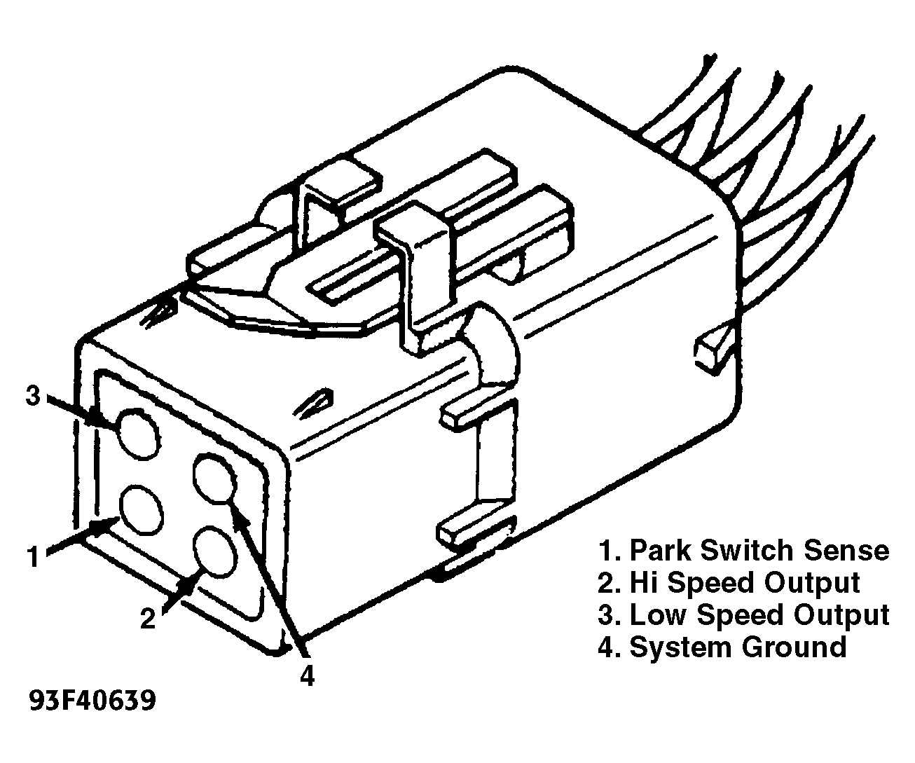
- Disconnect motor wire connector. To check motor low speed, using 2 jumper wires, connect one jumper between positive battery terminal and terminal No. 3 of motor connector. Connect other jumper wire to negative battery terminal and terminal No. 4 of motor connector. See Fig 3
. To check motor high speed, connect positive jumper to terminal No. 2 of motor connector. Connect negative jumper wire to terminal No. 4 of motor connector. If motor runs, go to step 4). If motor does not run, high or low speed, go to step 3).
- Using an ohmmeter, check for good ground at terminal No. 4 of motor wiring harness connector. See Fig 3
. If okay, replace motor. If ground is not okay, repair ground circuit as necessary.
- Using a voltmeter, check for battery voltage at terminal "D" of intermittent wiper relay in distribution center. If no voltage is present, check fuse "C". See Fig 2
. If okay, go to step 5). If not okay, repair as necessary.
 Courtesy of CHRYSLER CORP.
- Using an ohmmeter, check terminal "D" of HI-LO wiper relay to terminal No. 2 of wiring harness connector at motor for continuity. Check from terminal "E" of HI-LO wiper relay to terminal No. 3 of wiring harness connector at motor for continuity. If okay, go to step 7). If not, repair as necessary.
- Using an ohmmeter, check for continuity between HI-LO wiper relay and intermittent wiper relay. Check from terminal "B" of HI-LO wiper relay to terminal "B" of intermittent wiper relay. If okay, check for faulty relays. If not, repair as necessary.
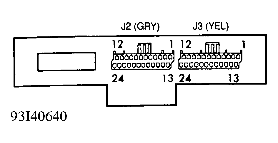
- Disconnect the Yellow 24-way J3 connector from body controller. See Fig 4
.
 Courtesy of CHRYSLER CORP.
- Using an ohmmeter, check for continuity from terminal No. 1 of J3 connector to terminal "C" of intermittent wiper relay. If okay, go to step 9). If not, repair as necessary.
- Using a voltmeter, with wiper switch connected, connect positive lead to terminal No. 1 of wiper switch. Turn ignition switch to ON position. Slowly move wiper switch from OFF position through each position to HIGH. If no voltage, replace wiper switch. If okay, check for continuity from terminal No. 1 of wiper switch to terminal No. 16 of body controller J3 connector. With ignition OFF, using and ohmmeter, check for continuity between fuse No. 10 and terminals No. 1 and 18 of body controller J3 connector. If no continuity, check HI-LO and intermittent relays. If okay, repair wire circuit as necessary. If voltage increases from zero to approximately 10-volts in HIGH position, replace body controller.
- Disconnect motor connector and replace fuse No. 10 from junction block. If fuse does not blow, go to step 2). If fuse blows, wiper control circuitry is at fault. Repair as necessary.