Solenoid, Pressure Control: Installation: Installation
 Courtesy of CHRYSLER GROUP, LLC
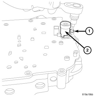
- Install the pressure control solenoid on to the valve body.
- Install the bolts (1) to the pressure control solenoid and tighten to 6 N.m (40 in. lbs.).
 Courtesy of CHRYSLER GROUP, LLC
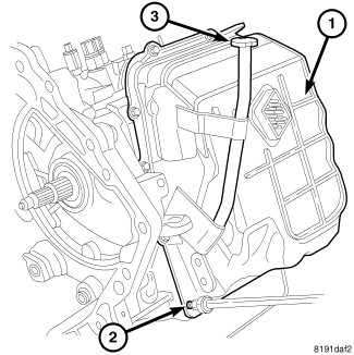
- Install the valve body oil pan, use a bead of MOPAR® ATF RTV (MS-GF41).
- Install the upper valve body oil pan bolts and tighten to 6 N.m (50 in. lbs.).
- Install the pressure tap at valve body oil pan and tighten to 6 N.m (50 in. lbs.).
- Lower the vehicle.
 Courtesy of CHRYSLER GROUP, LLC
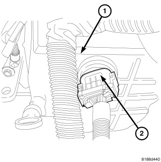
- Install the solenoid pack connector (2) at valve body oil pan.
- Raise and support the vehicle.
Courtesy of CHRYSLER GROUP, LLC
- Install the lower valve body oil pan bolts and tighten to 6 N.m (50 in. lbs.).
 Courtesy of CHRYSLER GROUP, LLC
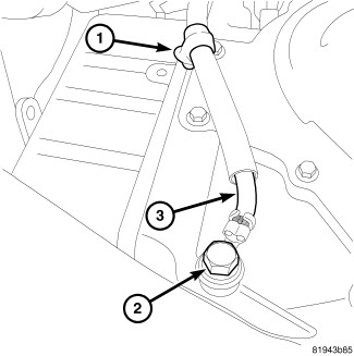
- Install the bolt at the ground cable and tighten to 10 N.m (90 in. lbs.).
- Install the clip to the valve body oil pan.
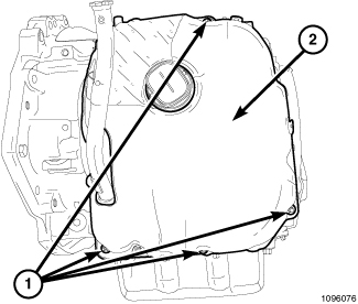 Courtesy of CHRYSLER GROUP, LLC
- Install the Front Sound Damper Cover (2) and fasteners (1).
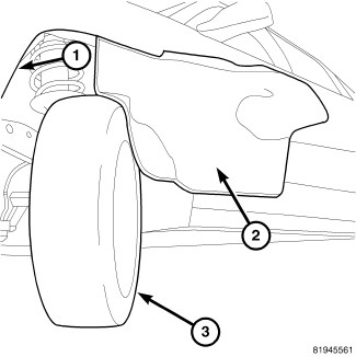 Courtesy of CHRYSLER GROUP, LLC
- Move left side inner wheel splash shield (2) into place.
- Install the left side inner wheel splash shield screws (1).
- Lower the vehicle.
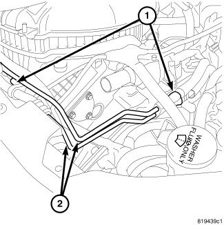 Courtesy of CHRYSLER GROUP, LLC
- Install the bolts (1) holding the power steering lines (2) and tighten to 10 N.m (90 in. lbs.).
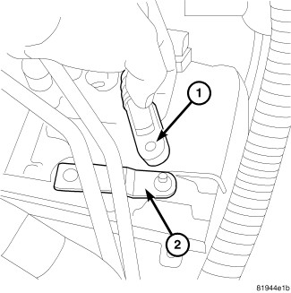 Courtesy of CHRYSLER GROUP, LLC
- Install shift cable (1) to manual lever (2).
 Courtesy of CHRYSLER GROUP, LLC
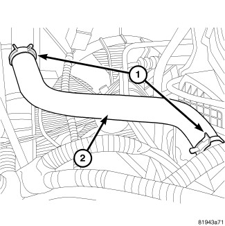
- Install upper radiator hose (2) and clamps (1).
- Fill the cooling system. Refer to STANDARD PROCEDURE
.
 Courtesy of CHRYSLER GROUP, LLC
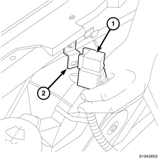
- Install the relay (1) at the core support.
- Install the battery and battery tray. Refer to BATTERY, INSTALLATION
.
- Install the battery cables.
- Fill transmission and road test. Refer to FLUID, STANDARD PROCEDURE .