DTC P0320: No Crank Reference Signal At Pcm: Testing
- Turn ignition on. Using scan tool, read CURRENT CKP COUNT while cranking engine. If CURRENT CKP COUNT changes while cranking engine, go to next step. If CURRENT CKP COUNT does not change while cranking engine, go to step 13
.
- Turn ignition off. Disconnect CKP sensor harness connector. See Fig 1
. Turn ignition on. Measure voltage between ground and 8-volt supply circuit (Orange wire) at CKP sensor harness connector. If voltage is more than 7.5 volts, go to next step. If voltage is 7.5 volts or less, go to step 9
.
- Turn ignition off. Measure resistance between ground and sensor ground circuit (Black/Light Blue wire) at CKP sensor harness connector. If resistance is less than 5 ohms, go to next step. If resistance is 5 ohms or more, check for open in Black/Light Blue wire between CKP sensor and PCM. Repair as necessary. If circuit is okay, replace PCM.
- Turn ignition on. Measure voltage between ground and signal circuit (Gray/Black wire) at CKP sensor harness connector. If voltage is less than 4.5 volts, go to next step. If voltage is 4.5-5.5 volts, replace CKP sensor. If voltage is more than 5.5 volts, repair short to voltage in Gray/Black wire between CKP sensor and PCM.
- Disconnect PCM harness connectors. See Figure
. Measure resistance between ground and signal circuit (Gray/Black wire) at CKP sensor harness connector. If resistance is 5 ohms or more, go to next step. If resistance is less than 5 ohms, repair short to ground in signal circuit.
- Measure resistance of signal circuit (Gray/Black wire) between CKP sensor harness connector and terminal No. 32 at PCM C1 harness connector. See Figure
. If resistance is less than 5 ohms, go to next step. If resistance is 5 ohms or more, repair open in signal circuit.
- Measure resistance between signal circuit (Gray/Black wire) and sensor ground circuit (Black/Light Blue wire) at CKP sensor harness connector. If resistance is 5 ohms or more, go to next step. If resistance is less than 5 ohms, repair short between signal circuit and sensor ground circuit.
- If no other possible causes are remaining, replace CKP sensor. Also, inspect slots on flywheel for damage. Repair as necessary.
- Turn ignition off. Disconnect PCM harness connectors. See Figure
. Measure resistance of 8-volt supply circuit (Orange wire) between CKP sensor harness connector and terminal No. 44 at PCM C2 harness connector. See Figure
. If resistance is less than 5 ohms, go to next step. If resistance is 5 ohms or more, repair open in 8-volt supply circuit.
- Measure resistance between ground and 8-volt supply circuit (Orange wire) at CKP sensor harness connector. If resistance is 5 ohms or more, go to next step. If resistance is less than 5 ohms, repair short to ground in 8-volt supply circuit.
- Measure resistance between 8-volt supply circuit (Orange wire) and signal circuit (Gray/Black wire) at CKP sensor harness connector. If resistance is 5 ohms or more, go to next step. If resistance is less than 5 ohms, repair short between 8-volt supply circuit and signal circuit.
- If no other possible causes are remaining, replace PCM.
- Turn ignition off. Visually inspect related wiring harness. Check for chafed, pierced, pinched or partially broken wires. Visually inspect related wiring harness connectors. Check for broken, bent, pushed out or corroded terminals. Refer to any Technical Service Bulletins (TSBs) that may apply. If a problem is found, repair as necessary. If no problems are found, go to next step.
- Using lab scope, backprobe CKP signal circuit (Gray/Black wire) at terminal No. 32 at PCM C1 connector. See Figure
and Figure
. Start engine. Monitor lab scope screen while wiggling wiring harness and connectors between CKP sensor and PCM. If any irregularities in lab scope pattern are present, carefully inspect related wiring harness connectors. Repair connectors as necessary. If connectors are okay, replace CKP sensor. If no irregularities in lab scope pattern are present, go to next step.
- Turn ignition off. Using lab scope, backprobe CMP sensor signal circuit (Tan/Yellow wire) at PCM C1 connector terminal No. 33. While observing lab scope screen, turn ignition on. If CMP sensor generated any pulses, replace CMP sensor. If CMP sensor did not generate any pulses, go to next step.
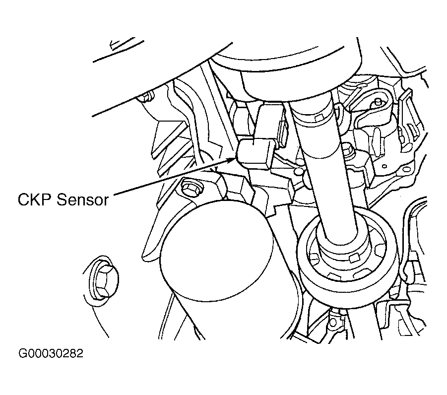 Courtesy of DAIMLERCHRYSLER CORPORATION