Test A: Identifying A/C-Heater System Problems
- Connect scan tool to Data Link Connector (DLC). See Fig 1. Using scan tool and the most current diagnostic program cartridge, ensure there is communication with Body Control Module (BCM) and Powertrain Control Module (PCM). If scan tool has a blank screen, go to next step. If any other communication problem exists, go to appropriate BODY CONTROL MODULES article in ACCESSORIES & EQUIPMENT.
If there are no communication problems, go to step 7.
- Turn ignition off. Disconnect scan tool from DLC. Check connector for an open, loose or disconnected terminals. Repair as necessary.
- Using a DVOM, ensure there is continuity between ground and DLC terminals No. 4 (Black wire) and No. 5 (Black/Light Green wire). If continuity is present, go to next step. If continuity is not present, repair wire(s) as necessary.
- Using a DVOM, check voltage at DLC terminal No. 16 (Pink wire). If battery voltage is not present, go to next step. If battery voltage is present, go to step 6.
- If battery voltage is not present, check fuse No. 19 (10-amp) located in junction block, behind end cover at left side of instrument panel. Replace fuse if blown. If fuse blows again, repair DLC battery feed circuit as necessary.
- Substitute scan tool cable with a known-good cable. If scan tool screen is no longer blank and scan tool is functioning properly, go to next step. If scan tool screen is still blank, replace defective scan tool. If there are no communication problems, go to next step.
- Using scan tool, select ENGINE, and then READ DTCS. If scan tool does not display any PCM DTCs, go to next step. See appropriate SELF-DIAGNOSTICS article in ENGINE PERFORMANCE
if any of the following A/C-heater system related PCM DTCs are displayed:
- ECT SENSOR VOLTAGE TOO LOW
- ECT SENSOR VOLTAGE TOO HIGH
- A/C PRESSURE SENSOR VOLTAGE TOO HIGH
- A/C PRESSURE SENSOR VOLTAGE TOO LOW
- LOW SPEED FAN CONTROL RELAY CIRCUIT
- HIGH SPEED FAN CONTROL RELAY CIRCUIT
- A/C CLUTCH RELAY CIRCUIT
- ENGINE IS COLD TOO LONG
- Using scan tool, select BODY SYSTEM, BODY COMPUTER, SENSORS and then IGNITION VOLTAGE. Turn ignition on. If battery voltage is displayed, go to next step. If battery voltage is not displayed, go to appropriate BODY CONTROL MODULES article in ACCESSORIES & EQUIPMENT.
- Using scan tool, select BODY SYSTEM, BODY COMPUTER, and then READ DTCS. If A/C-heater system related BCM DTCs are not present, go to next step. If A/C-heater system related BCM DTCs are present, go to TEST B: IDENTIFYING A/C-HEATER SYSTEM BCM DTCS .
- If no BCM DTCs exist and mode door is inoperative, go to TEST Q: MODE DOOR FEEDBACK FAILURE in AUTOMATIC A/C-HEATER SYSTEMS - CONCORDE, INTREPID, LHS & 300M article. If no BCM DTCs exist and temperature control/blend air door is inoperative, go to TEST J: BLEND FEEDBACK FAILURE in AUTOMATIC A/C-HEATER SYSTEMS - CONCORDE, INTREPID, LHS & 300M article.
- If no BCM DTCs exist and mode door is inoperative, go to TEST Q: MODE DOOR FEEDBACK FAILURE in AUTOMATIC A/C-HEATER SYSTEM - CONCORDE, INTREPID, LHS & 300M article.
If no BCM DTCs exist and recirculation door is inoperative, go to TEST T: RECIRCULATION DOOR TEST FAILURE in AUTOMATIC A/C-HEATER SYSTEMS - CONCORDE, INTREPID, LHS & 300M article.
- If rear window defogger is inoperative, see appropriate REAR WINDOW DEFOGGERS article in ACCESSORIES & EQUIPMENT.
- If no BCM DTCs exist and blower motor is inoperative, go to TEST I: INOPERATIVE BLOWER MOTOR . If no BCM DTCs exist and blower motor speed(s) are incorrect, go to TEST K: INCORRECT BLOWER MOTOR SPEEDS . If no BCM DTCs exist and either A/C switch or rear defogger switch is inoperative, go to TEST M: INOPERATIVE CONTROL HEAD SWITCH .
- If no BCM DTCs exist and there is a problem with A/C-heater control head illumination, but instrument panel lights operate properly, go to TEST L: CONTROL HEAD ILLUMINATION . If instrument panel lights do not operate properly, see ILLUMINATION/INTERIOR LIGHTS article in ACCESSORIES & EQUIPMENT.
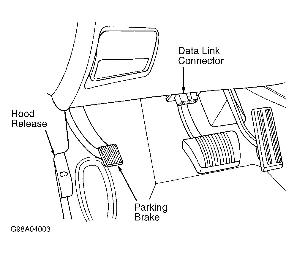 Courtesy of CHRYSLER CORP.