- Clean and inspect the fuel injectors and the fuel injection fuel rail. Do not remove the fuel injector from the fuel rail. Refer to Fuel Injector and Fuel Injector Bore Cleaning and Inspection
- EN-51146-2-2
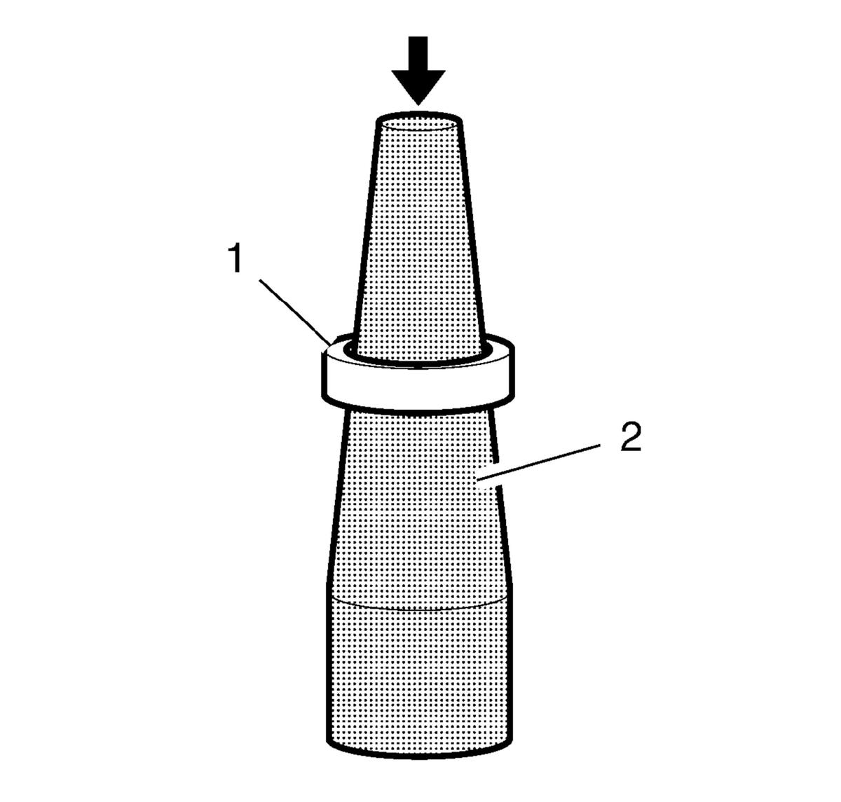
mounting sleeve-long (2) @ Fuel Injector - Install
 Courtesy of GENERAL MOTORS COMPANY
- Install a NEW fuel injector combustion seal (1) to the EN-51146-2-2
mounting sleeve-long (2).
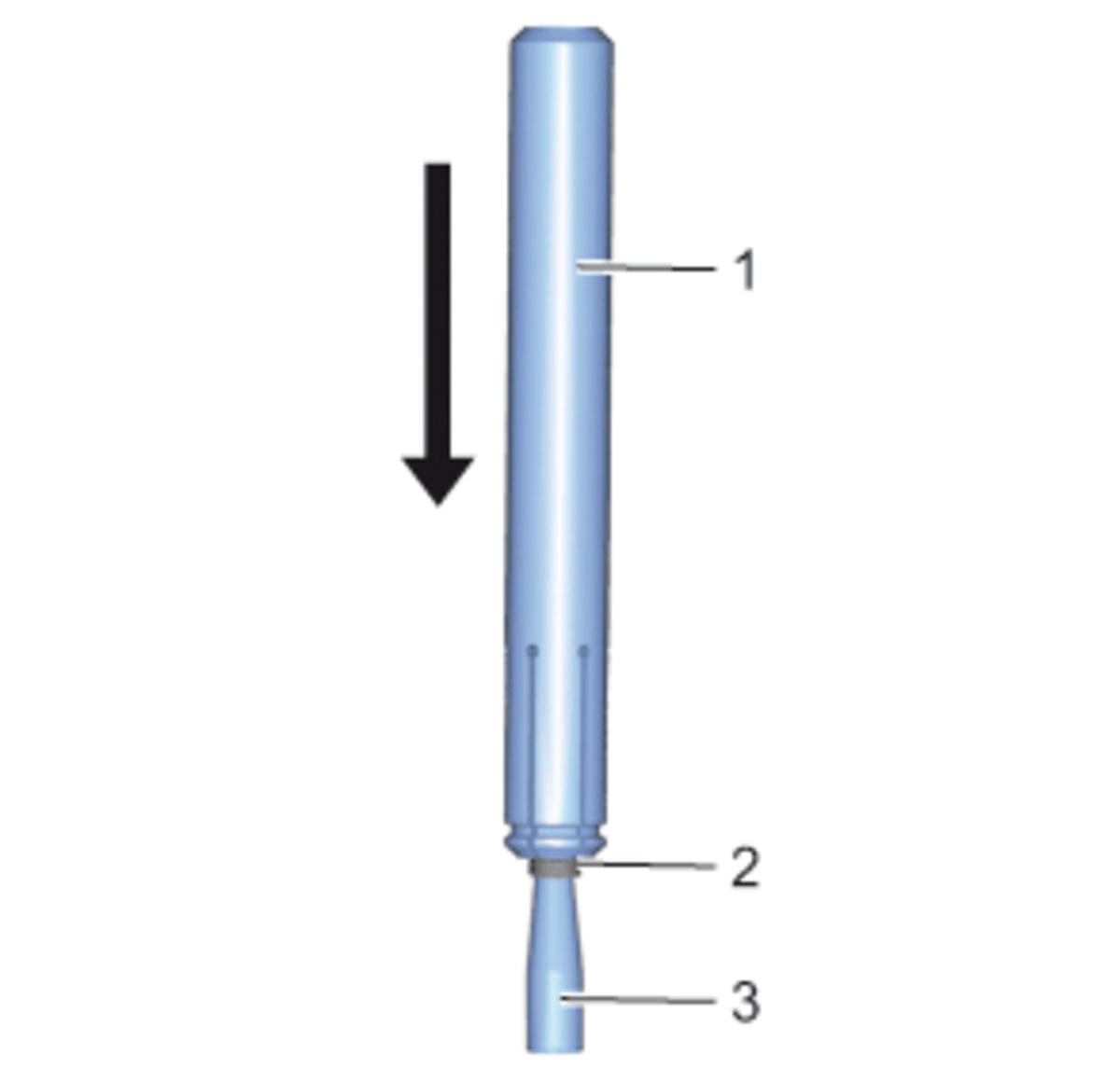
- Use the EN-51146-2-6-1
slider outside (1) to push the fuel injector combustion seal (2) down onto the EN-51146-2-2
mounting sleeve-long (3).
 Courtesy of GENERAL MOTORS COMPANY
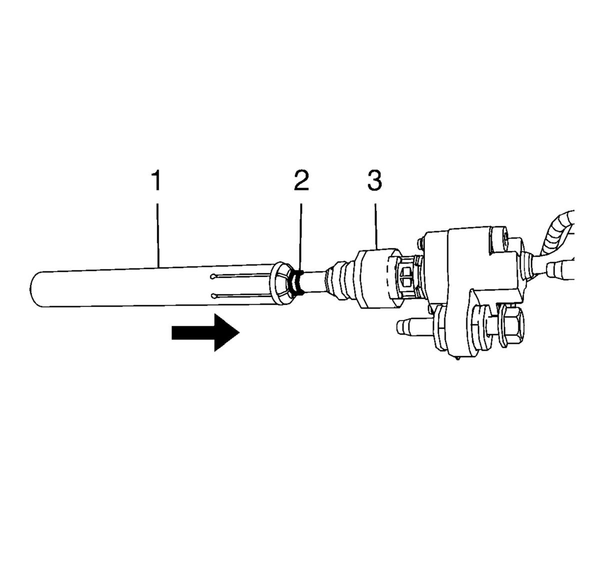
- Use the EN-51146-2-6-1
slider outside (1) to install the fuel injector combustion seal (2) to the Fuel Injector (3).
 Courtesy of GENERAL MOTORS COMPANY
- EN-51146-2-6-1
slider outside (1) @ EN-51146-2-2
mounting sleeve-long - Remove
- EN-51146-2-2
mounting sleeve-long @ Fuel Injector (3) - Remove
- EN-51146-2-3
mounting sleeve-short @ Fuel Injector (3) - Install
- Install a NEW fuel injector combustion seal to the EN-51146-2-3
mounting sleeve-short.
- Use the EN-51146-2-6-1
slider outside (1) to push the fuel injector combustion seal down onto the EN-51146-2-2
mounting sleeve-short.
- Use the EN-51146-2-6-1
slider outside (1) to install the fuel injector combustion seal to the Fuel Injector (3).
- EN-51146-2-6-1
slider outside (1) @ EN-51146-2-2
mounting sleeve-short - Remove
- EN-51146-2-3
mounting sleeve-short @ Fuel Injector (3) - Remove
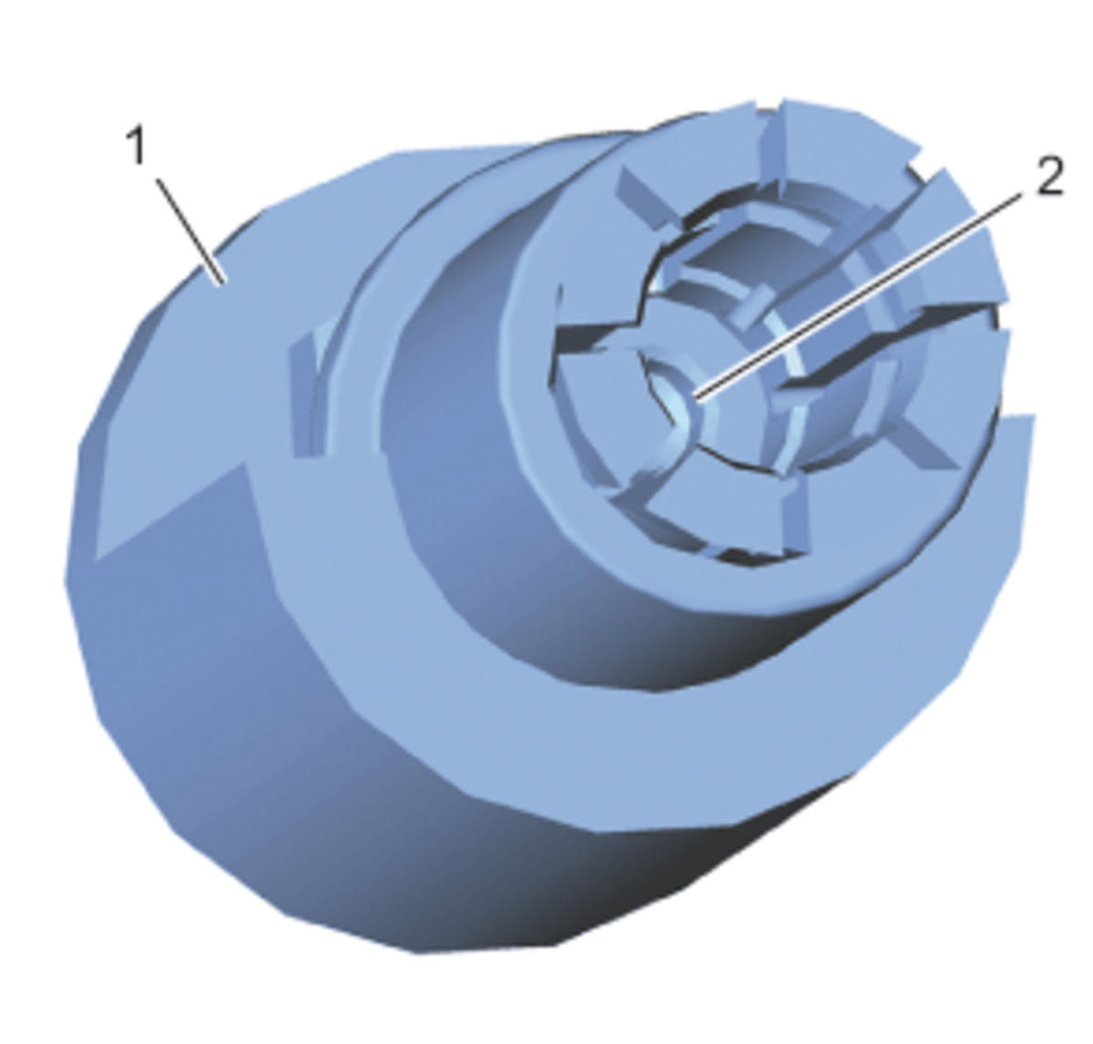
- Before using the EN-51146 - 2 - 4
pre-sizing tool (1), check if the fuel injector limiter (2) is in the right position.
 Courtesy of GENERAL MOTORS COMPANY
- Push the EN-51146-2-4
pre-sizing tool (1) over the fuel injector (2).
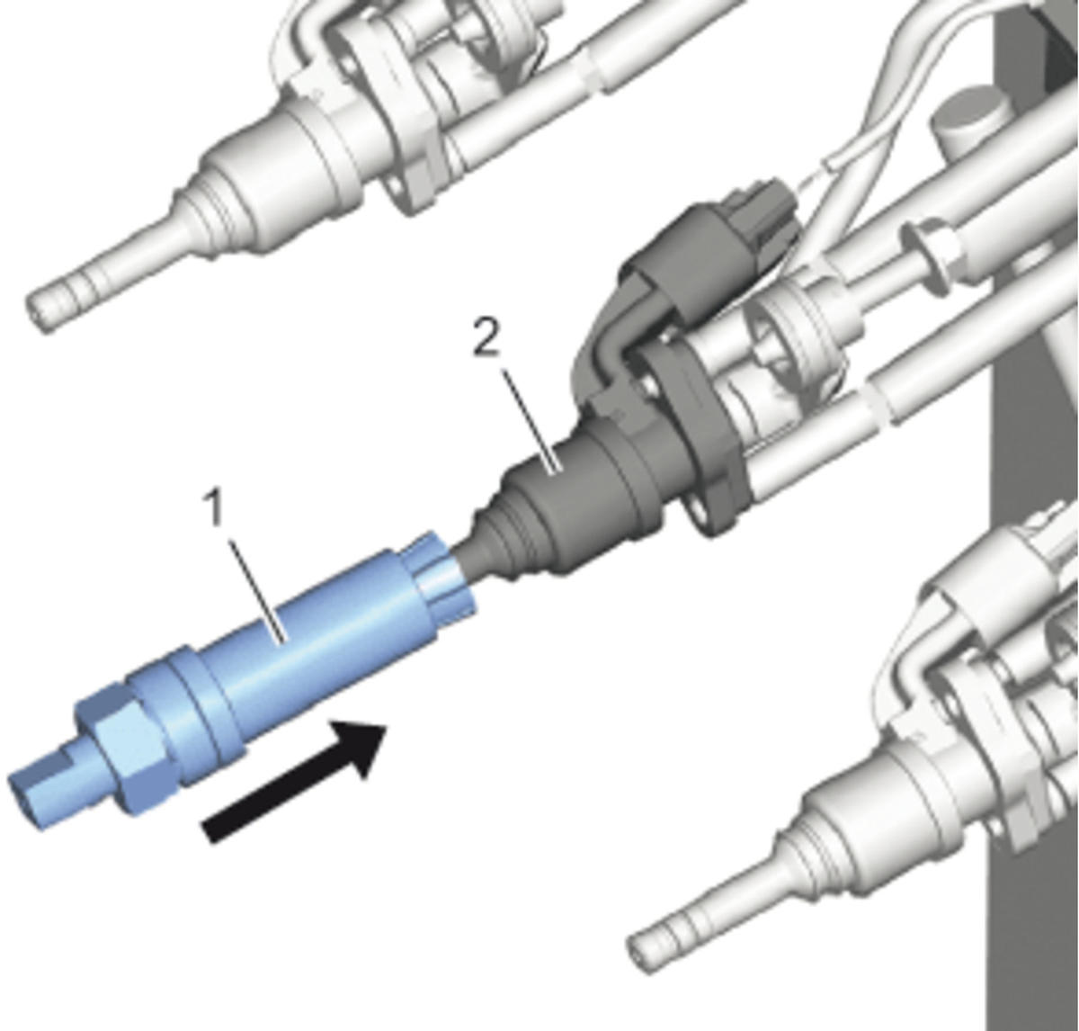 Courtesy of GENERAL MOTORS COMPANY
NOTE:
Pre-form the fuel injector combustion seals by hand prior to using the sizing tool.
- Tighten the nut (2) and counterhold at the spanner flat of the EN-51146-2-4
pre-sizing tool thread (1) until the measure (a) of 4.5 mm (0.177 in) is reached.
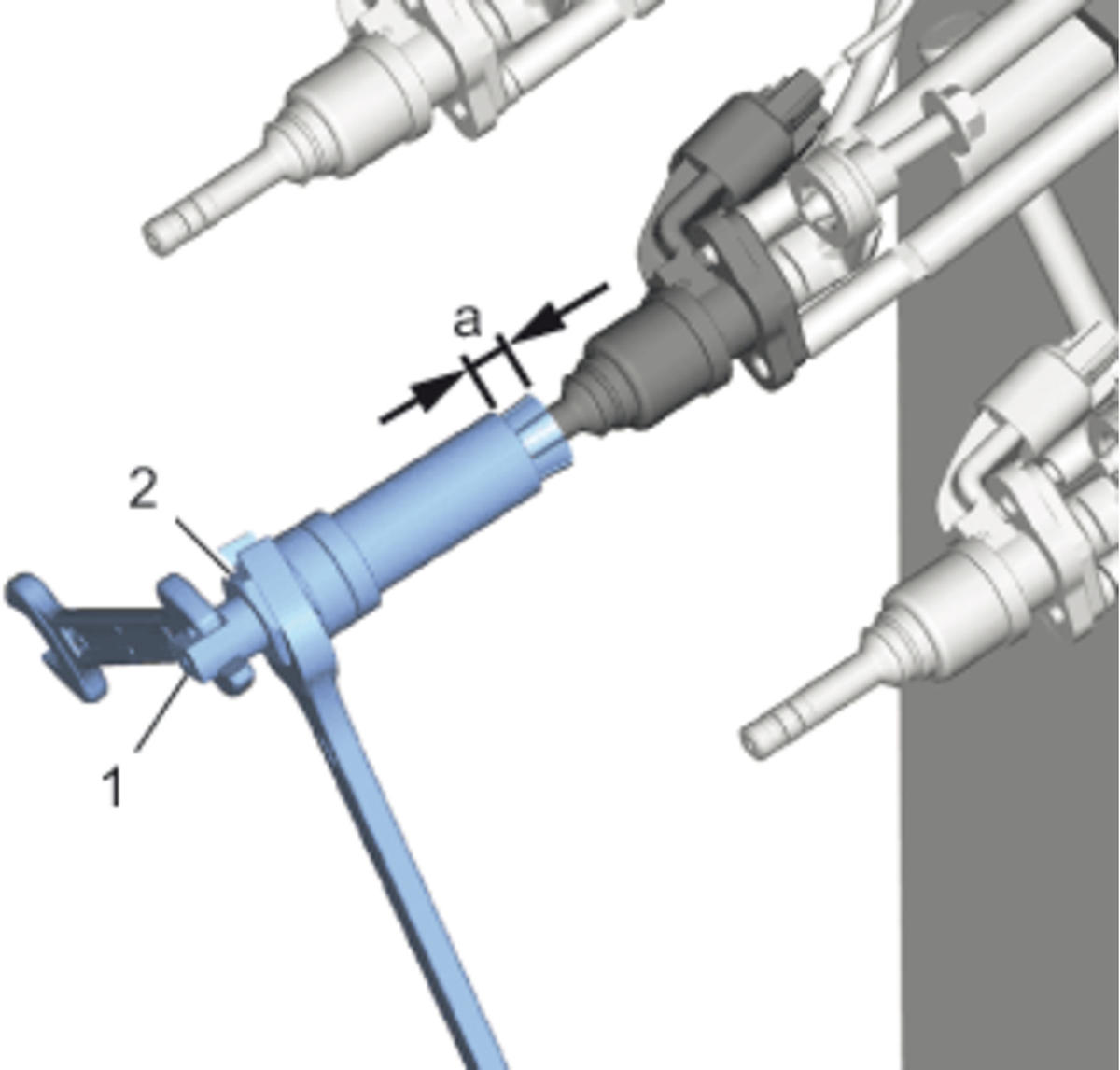 Courtesy of GENERAL MOTORS COMPANY
- Loosen the nut (2) of the EN-51146-2-4
pre-sizing tool.
- Install the EN-51146-2-4-7
take off chassis (2) to the EN-51146-2-4
pre-sizing tool (3).
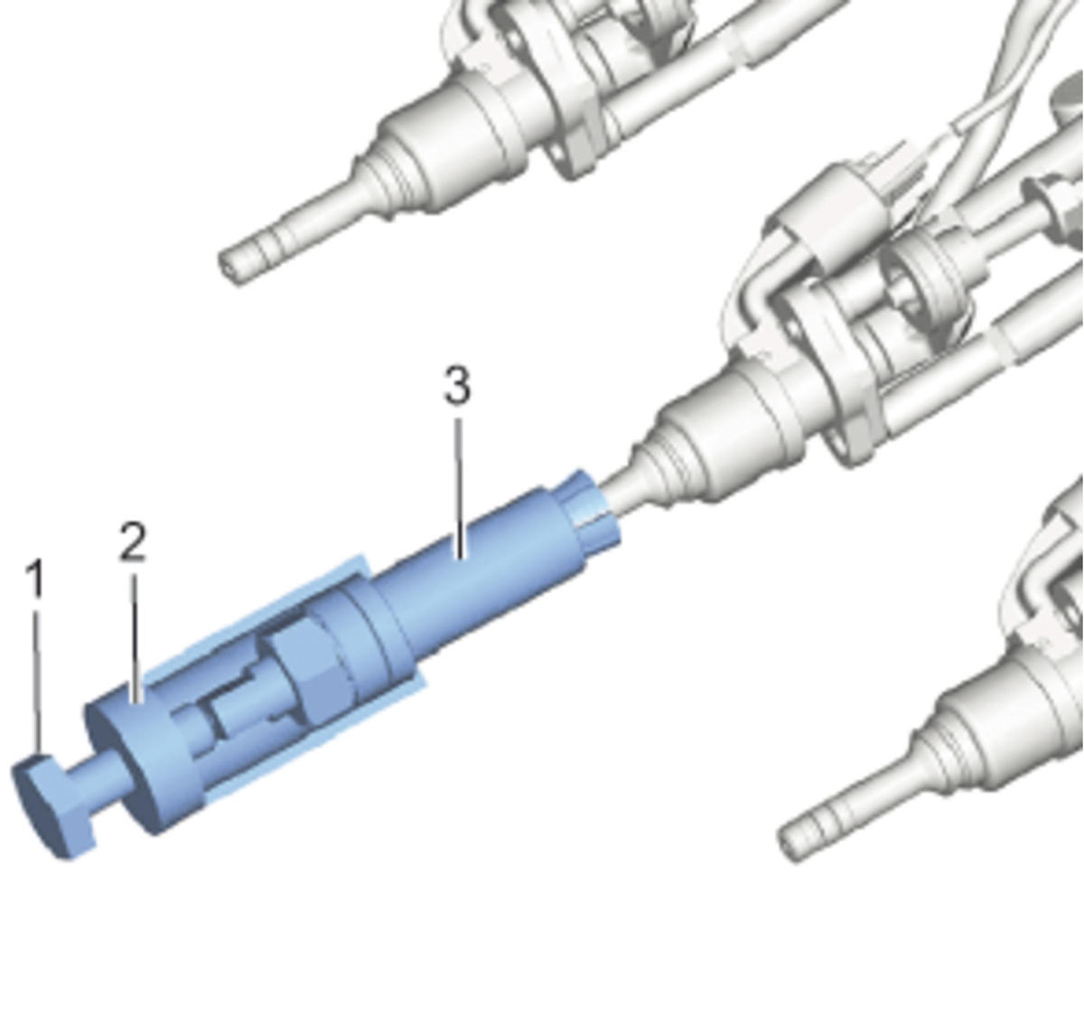 Courtesy of GENERAL MOTORS COMPANY
- Install the EN-51146-2-4-6
screw M10 (1) to the EN-51146-2-4-7
take off chassis (2) and tighten until the EN-51146-2-4
pre-sizing tool (3) is loosened.
- EN-51146-2-5
calibration tool (2) @ Fuel Injector (1) - Install
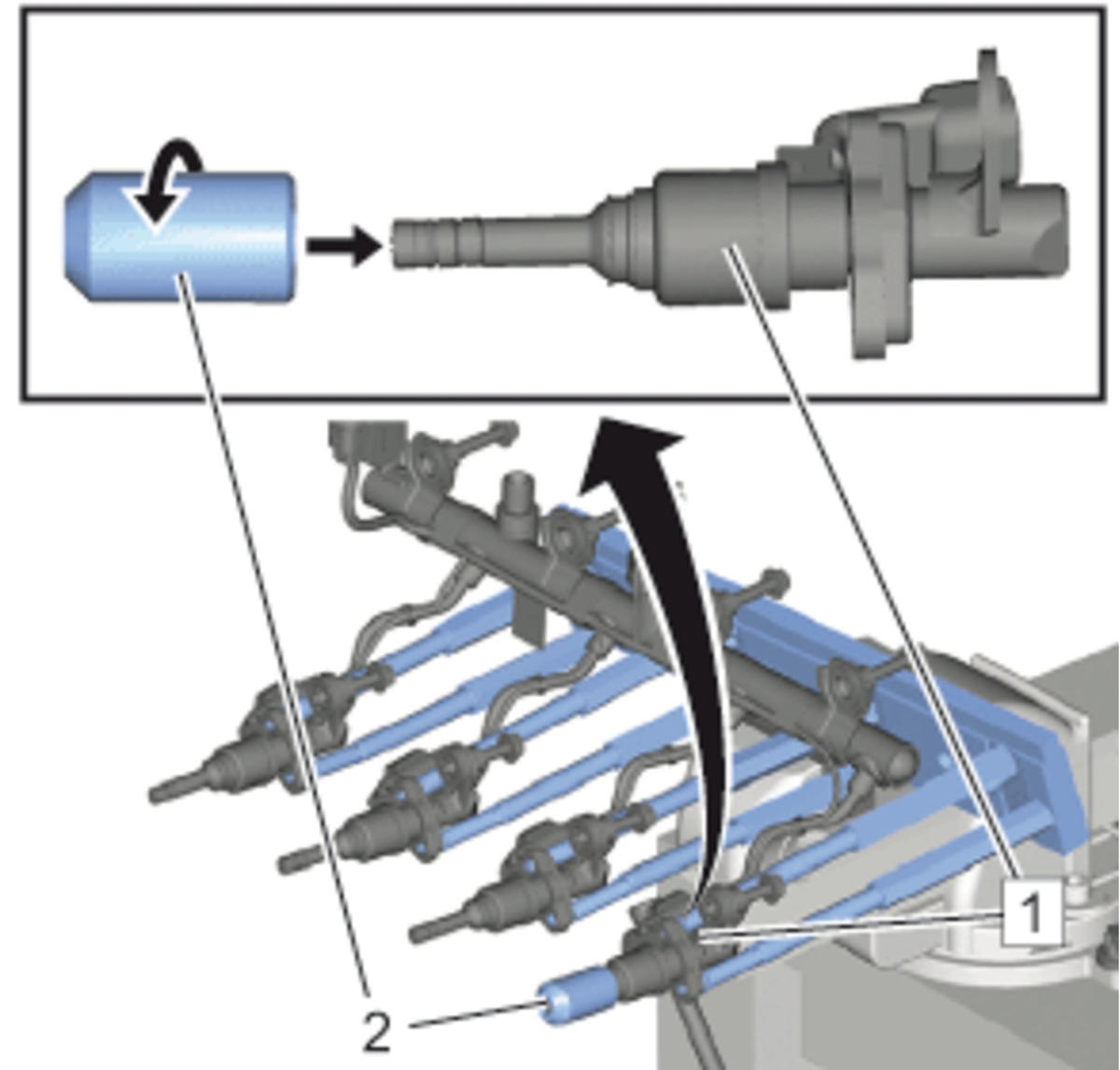 Courtesy of GENERAL MOTORS COMPANY
- EN-51146-2-5
calibration tool (2) @ Fuel Injector (1) - Remove
- Check the fuel injector combustion seals (2 seals each fuel injector) for correct seat:
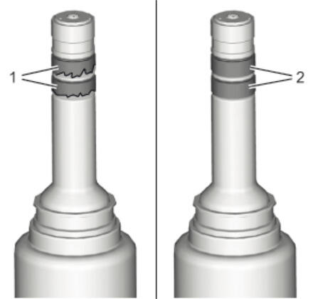 Courtesy of GENERAL MOTORS COMPANY
WARNING:
The fuel injector seals must fit properly in the relative groove. Overlapping of the fuel injector seals with the external surface of the injector must be avoided. If the seals are installed incorrectly, it could cause leaks and risk of injury.
- The seal must not be too large, buckled or corrugated (1).
- The seal must be fixed tight and accurate (2).
- If the seals are installed not correctly, repeat the steps 24 - 27 of the removal procedure and the steps 1 - 22 of the installation procedure.
- Repeat 1 - 23 of the installation procedure for the remaining fuel injectors.
- EN-51146-2-5
calibration tool (2) @ Fuel Injector (1) - Install [4x]
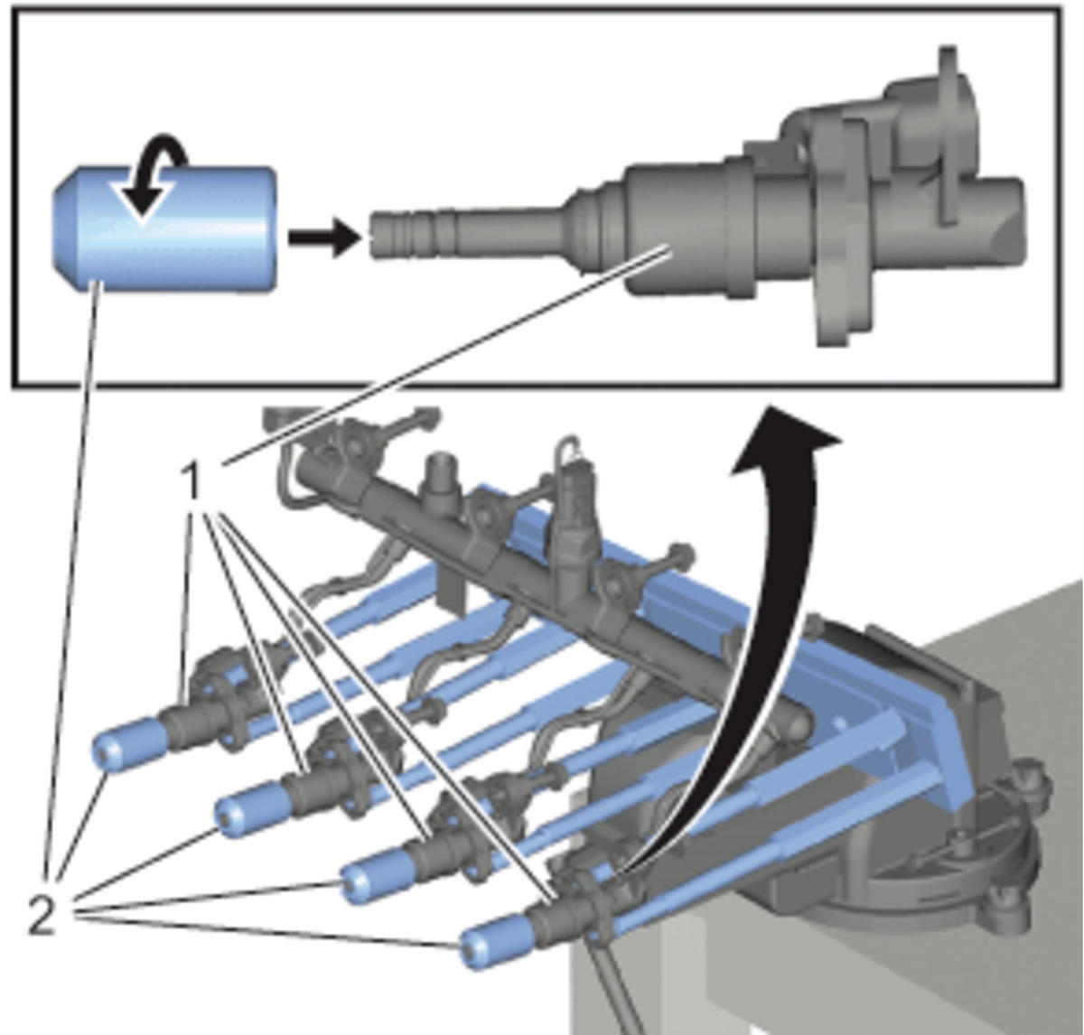 Courtesy of GENERAL MOTORS COMPANY
- Remove the fuel injector assembly with the EN-51146-1-2
plate from the bench vise.
- Plate Bolt (1) - Remove [8x]
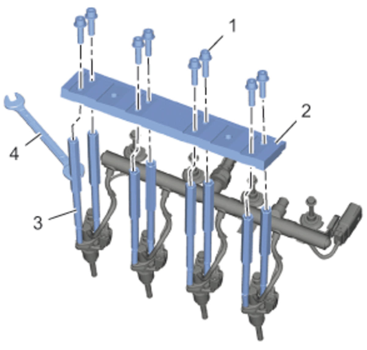 Courtesy of GENERAL MOTORS COMPANY
NOTE:
Use a wrench (4) to counter hold the EN-51146-1-1
support (3)
- EN-51146-1-2
plate (2) - Remove
- EN-51146-1-1
support (2) @ Fuel Injector (3) - Remove
NOTE:
Never loosen both EN-51146-1-1
supports at the same time. Doing so could cause leaks or malfunction after installation. It is only possible, when the fuel injector will be replaced.
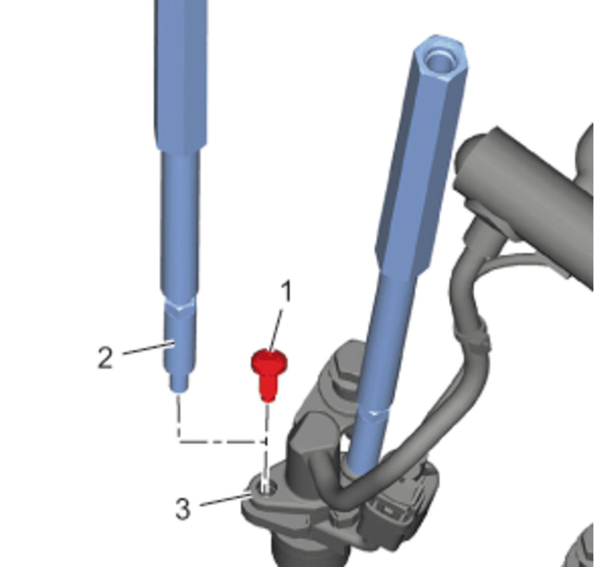 Courtesy of GENERAL MOTORS COMPANY
- Apply thread locker to the NEW fuel injector bolt (1). Refer to Adhesives, Fluids, Lubricants and Sealers
NOTE:
DO NOT reuse the old fuel injector bolt.
- Install NEW fuel injector bolt (1) to the fuel injector (3) and tighten to 5 N.m (44 lb in).
- EN-51146-1-1
support (1) @ Fuel Injector (3) - Remove
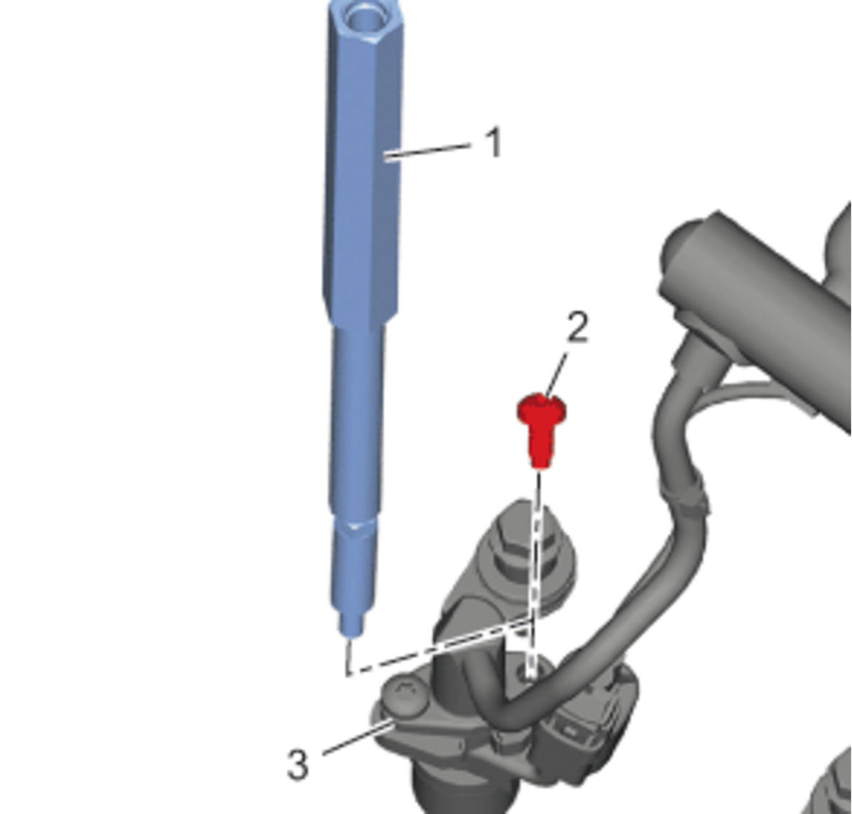 Courtesy of GENERAL MOTORS COMPANY
- Apply thread locker to the NEW fuel injector bolt (2). Refer to Adhesives, Fluids, Lubricants and Sealers
NOTE:
DO NOT reuse the old fuel injector bolt.
- Install a NEW fuel injector bolt (2) to the fuel injector (3) and tighten to 5 N.m (44 lb in).
- Repeat the steps 29 - 34 for the remaining injectors.
- Clean the fuel injector bores at the cylinder head. Refer to Fuel Injector and Fuel Injector Bore Cleaning and Inspection
- Check the fuel injector rail assembly:
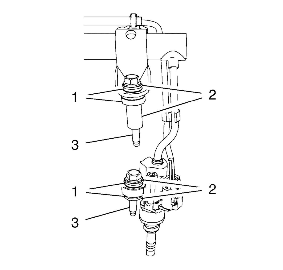 Courtesy of GENERAL MOTORS COMPANY
- Check the fuel injectors for damage.
- Check the fuel injector seals for correct seating.
- Check if all bolts (3) with decoupling elements (1) and retainer (2) are complete.
- EN-51146-2-5
calibration tool (2) @ Fuel Injector (1) - Remove [4x]
- Carefully Install the fuel rail assembly (1).
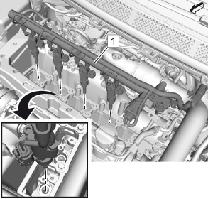 Courtesy of GENERAL MOTORS COMPANY
CAUTION:
During the installation of the fuel rail and injector assembly, ensure that the fuel injectors are positioned straight into the injector opening. Failure to follow this caution can tilt or bend the injectors and could cause leaks or malfunction after installation.
- Push the fuel injectors lightly into their seats.
- Tighten the 10 fuel rail bolts (1) in the sequence as shown to 10 N.m (89 lb in).
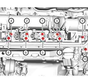 Courtesy of GENERAL MOTORS COMPANY
- Retainer (2) - Install
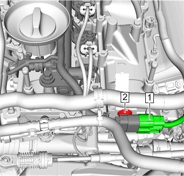 Courtesy of GENERAL MOTORS COMPANY
- Fuel Injection Fuel Rail Wiring Harness (1) - Connect
- Ignition Coil - Install [4x] Ignition Coil Replacement
- Fuel Injection Fuel Feed Front Pipe - Install Fuel Injection Fuel Feed Front Pipe Replacement
- Perform a fuel rail assembly leak test.
WARNING:
Fuel escapes - observe safety measures and national legislation. Failure to comply could result in personal injury.
NOTE:
Ensure that all work at the engine is finished.
- Start the engine.
- Check the fuel system for escaping fuel.