Mike's Workshop Manuals: Service manuals for every vehicle
Home >> Chevrolet >> 2008 >> Chevy Express G2500, Van Cargo Extended, 6.6 6 >> Repair and Diagnosis >> Engine Performance >> System >> Engine Control System & Fuel System - 6.6L (LMM) - Introduction (2 Of 2) >> Schematic and Routing Diagrams >> Engine Controls Schematics
Engine Controls Schematics

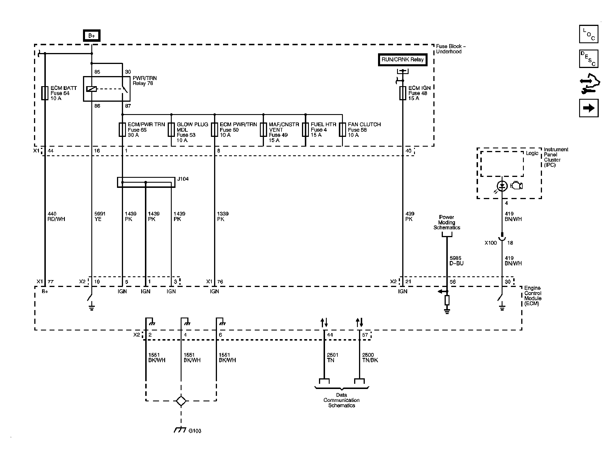
Fig 1: Module Power, Ground, Serial Data, and MIL Schematic
GM1878790Courtesy of GENERAL MOTORS CORP.
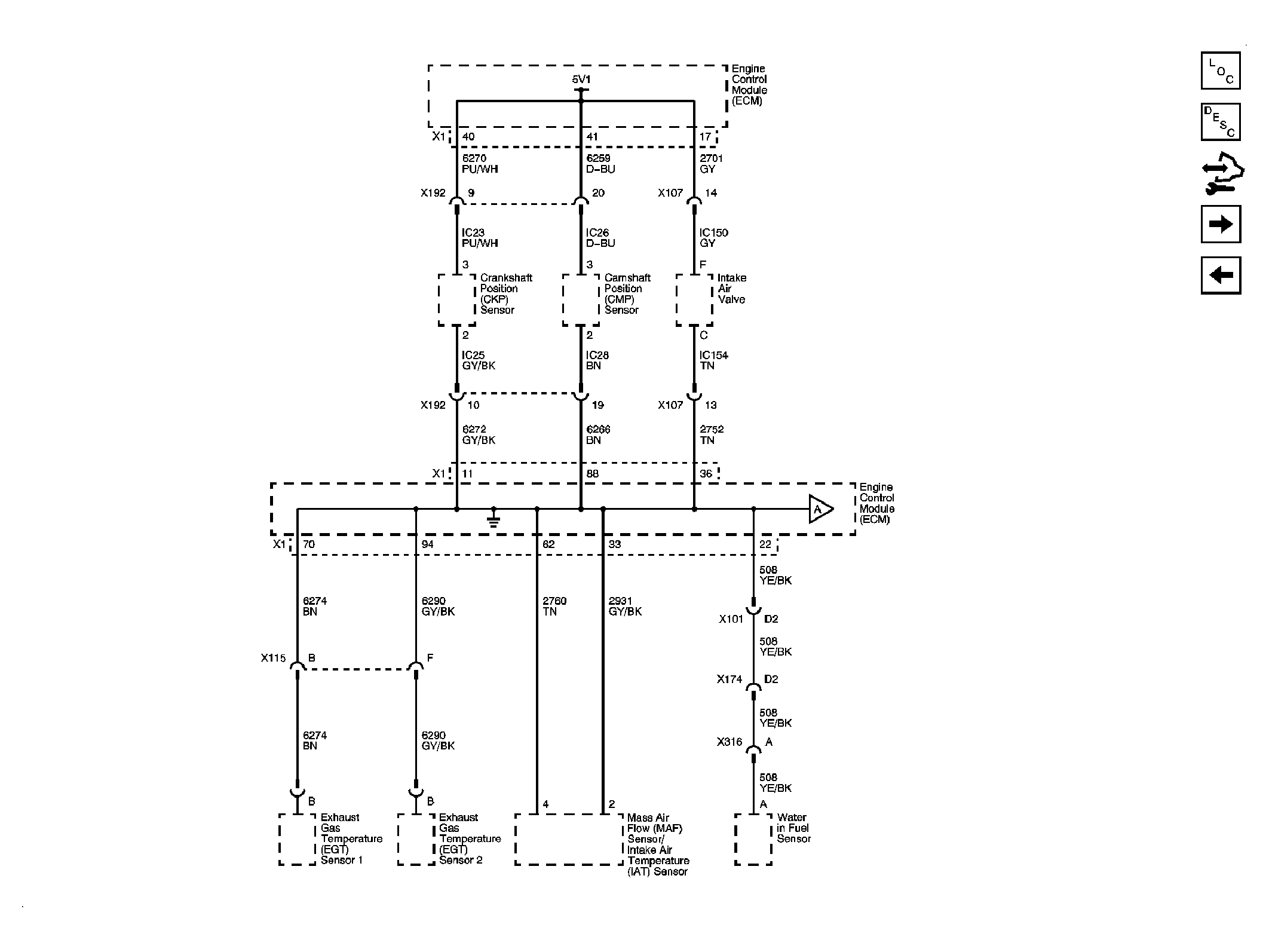
Fig 2: Engine Data Sensors - 5-Volt and Low References Schematic 1 of 2
GM1878796Courtesy of GENERAL MOTORS CORP.
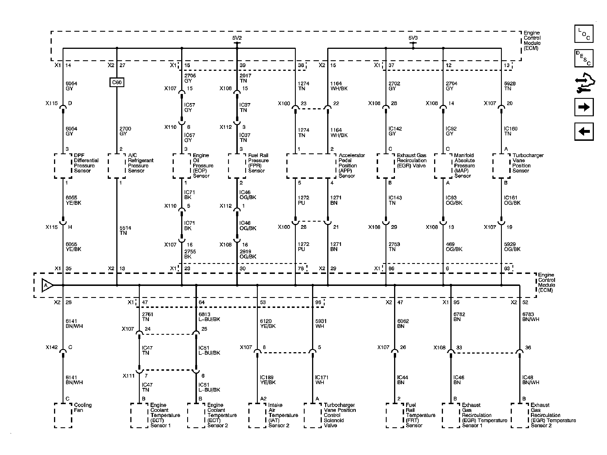
Fig 3: Engine Data Sensors - 5-Volt and Low References Schematic 2 of 2
GM1878799Courtesy of GENERAL MOTORS CORP.
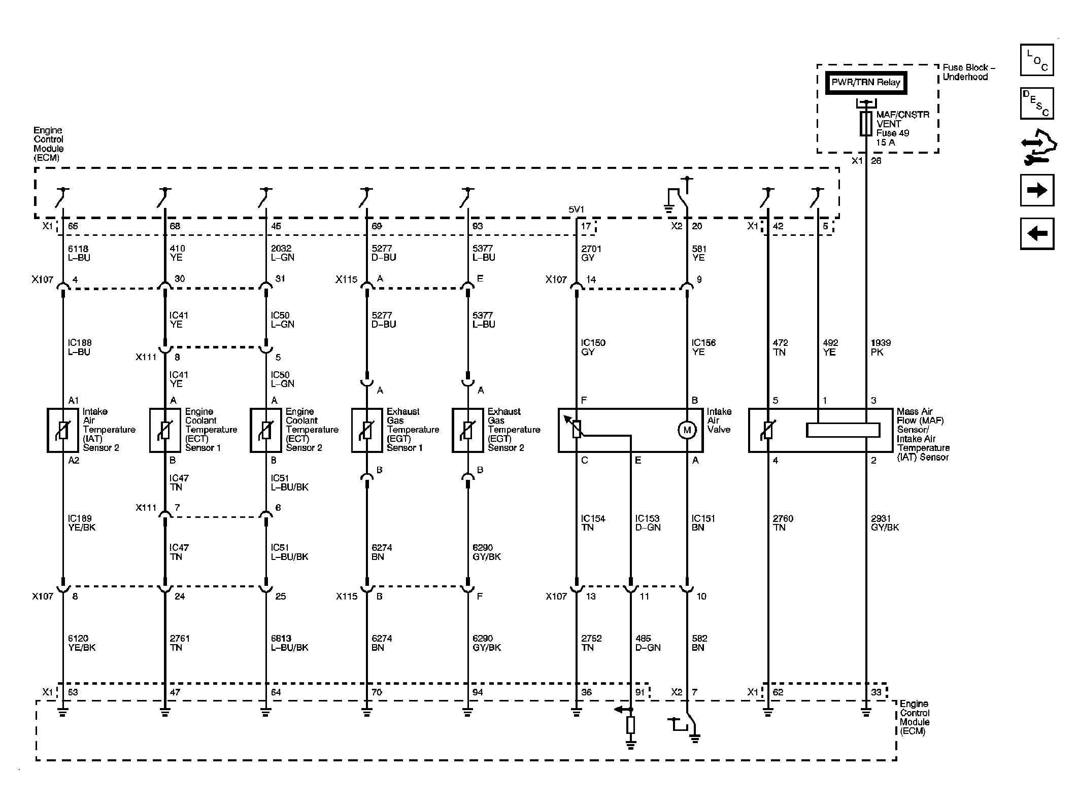
Fig 4: Engine Data Sensors - Temperature, AI, and MAF Schematic
GM1878802Courtesy of GENERAL MOTORS CORP.
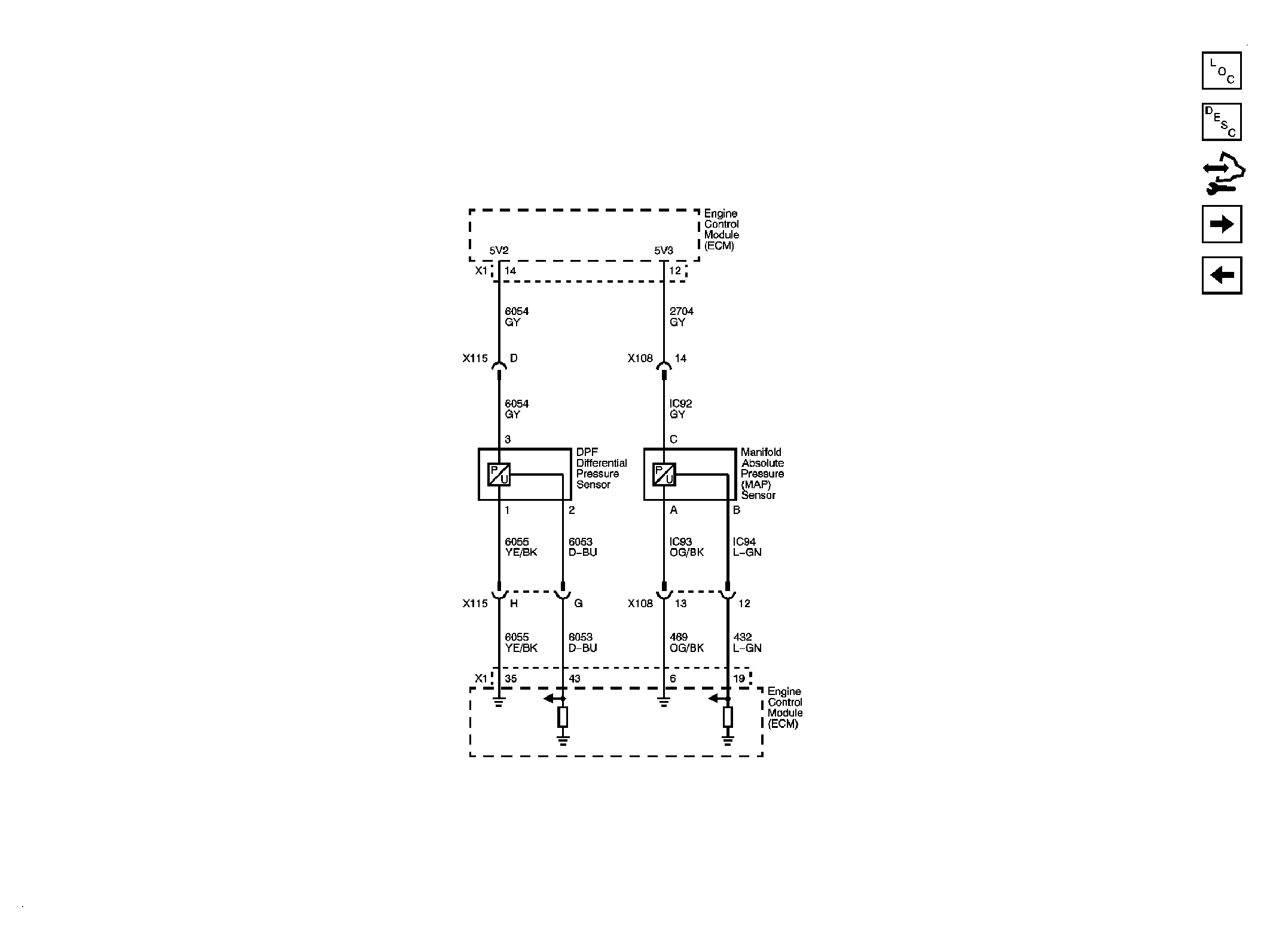
Fig 5: Engine Data Sensors - Pressure, and High Idle Switch Schematic
GM1878807Courtesy of GENERAL MOTORS CORP.
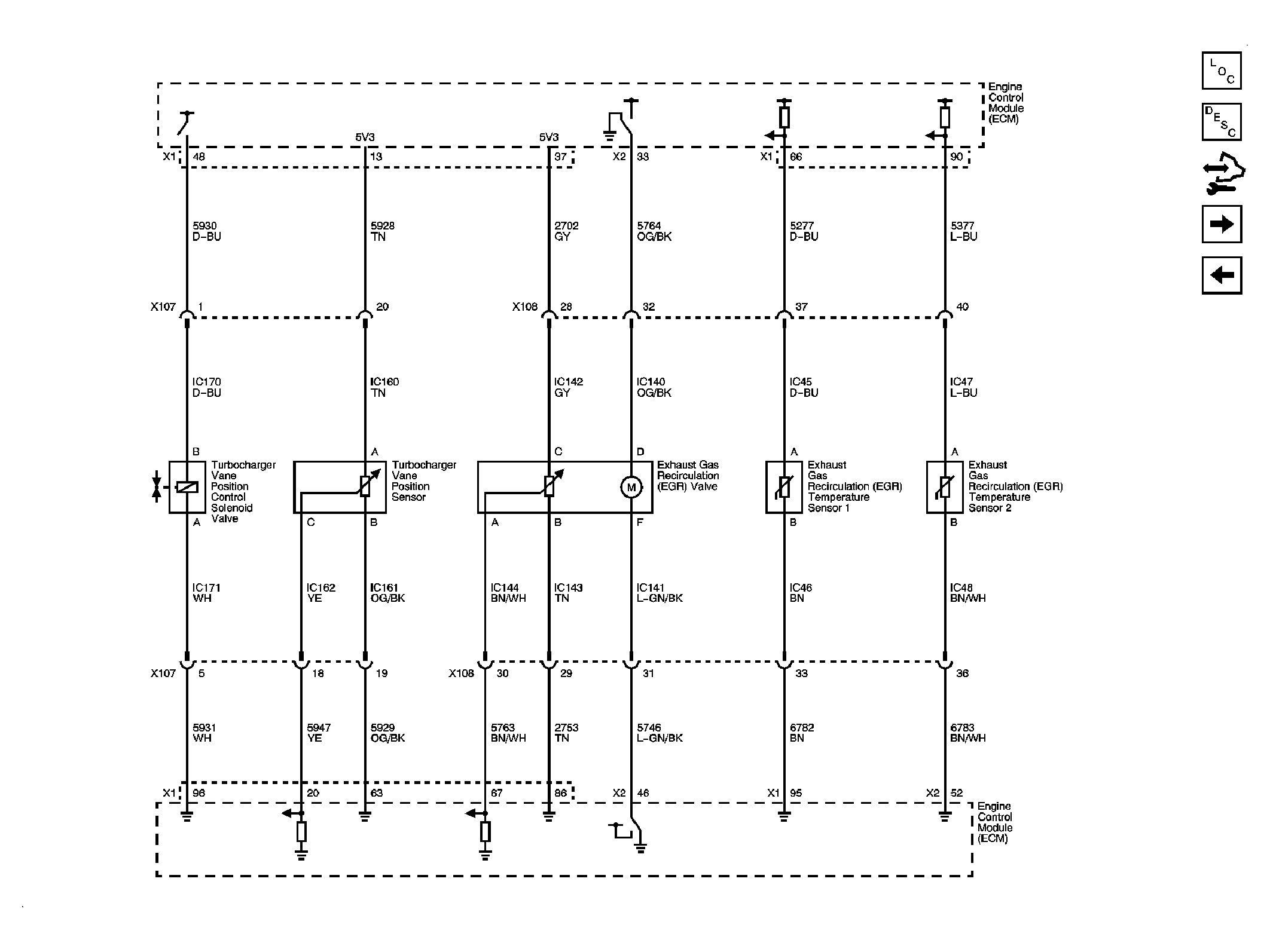
Fig 6: Engine Data Sensors - EGR and Turbocharger Controls Schematic
GM1878812Courtesy of GENERAL MOTORS CORP.
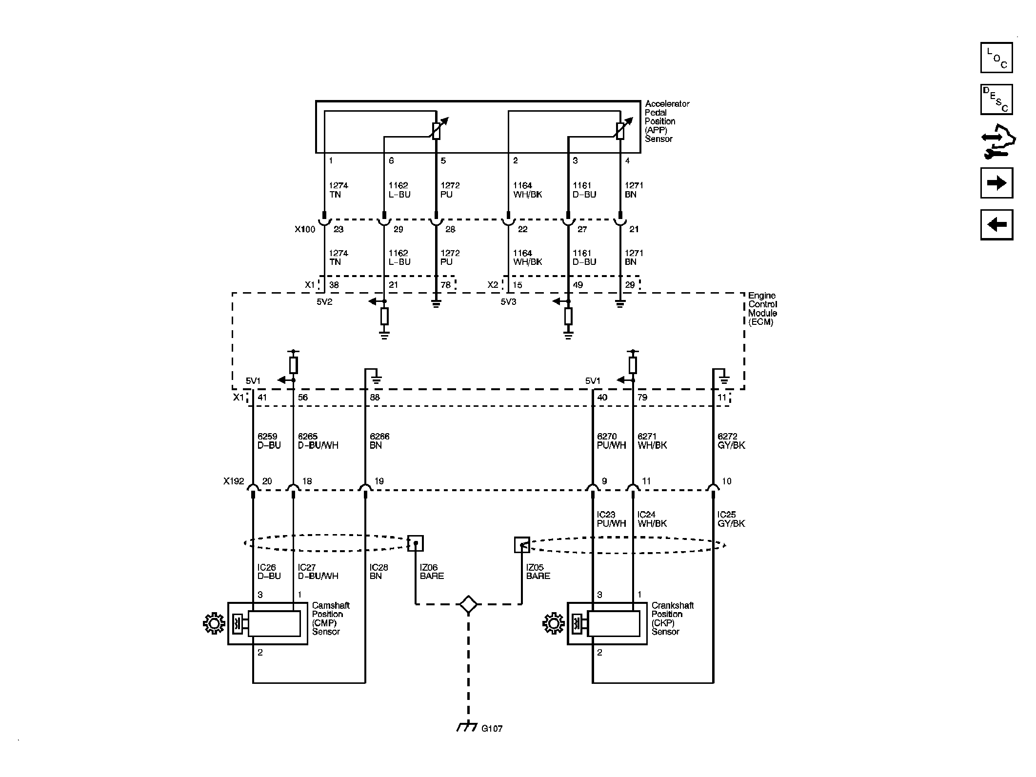
Fig 7: Engine Data Sensors - Pedal Position and Injector Timing Schematic
GM1878817Courtesy of GENERAL MOTORS CORP.
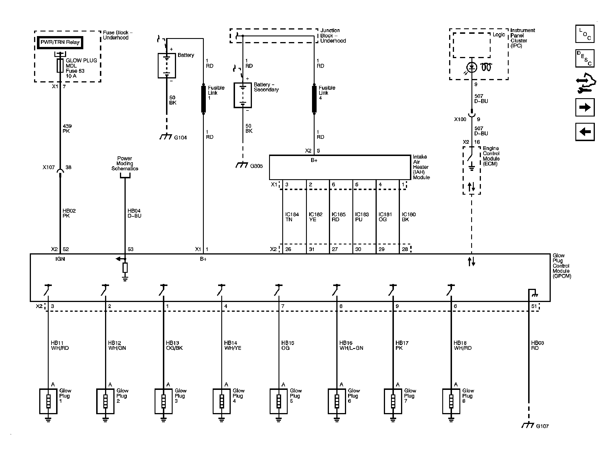
Fig 8: Engine Data Sensors - Glow Plug Controls Schematic
GM1878819Courtesy of GENERAL MOTORS CORP.
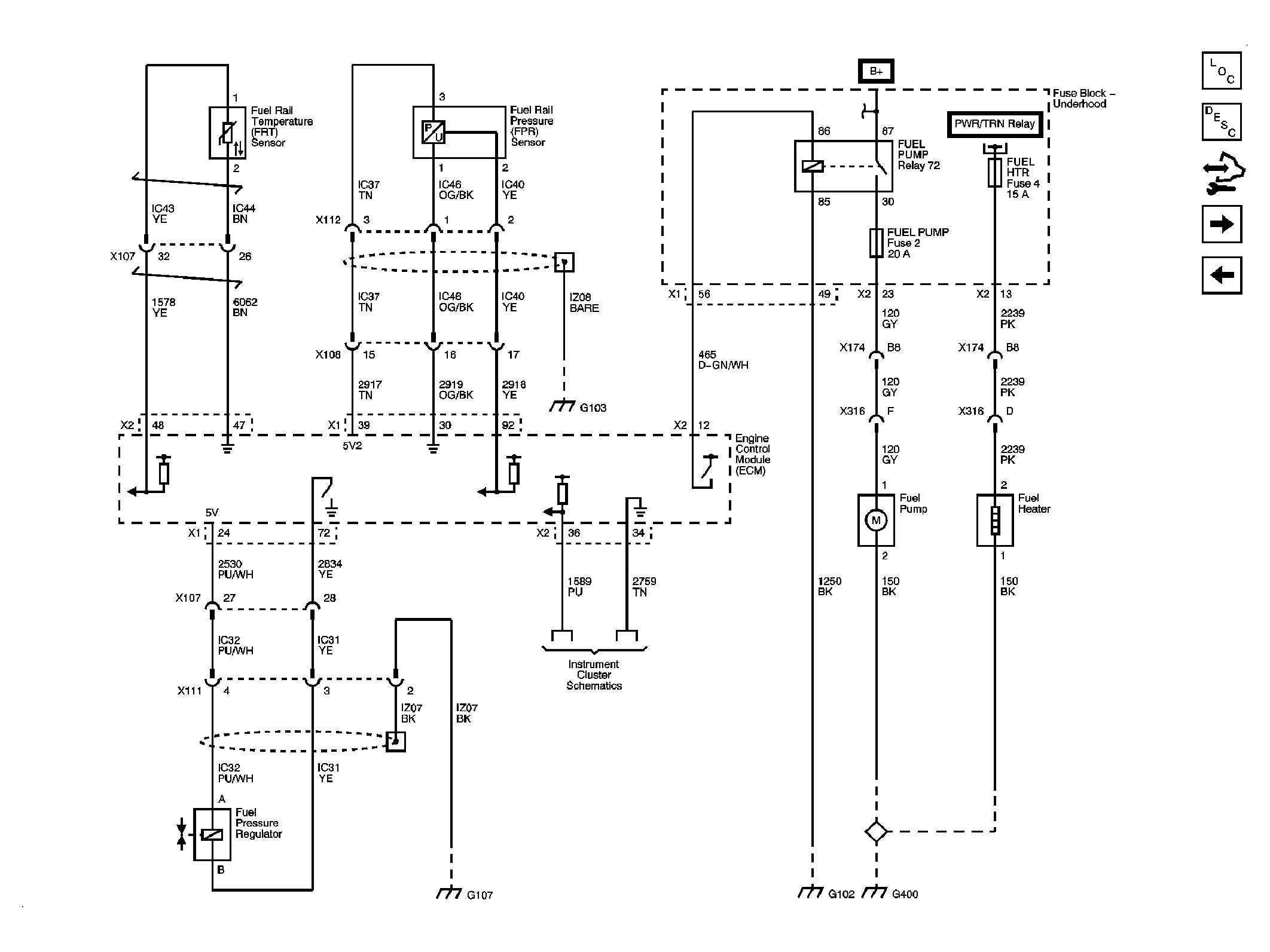
Fig 9: Fuel Controls - Fuel Pump, Temperature, and Pressure Controls Schematic
GM1878824Courtesy of GENERAL MOTORS CORP.
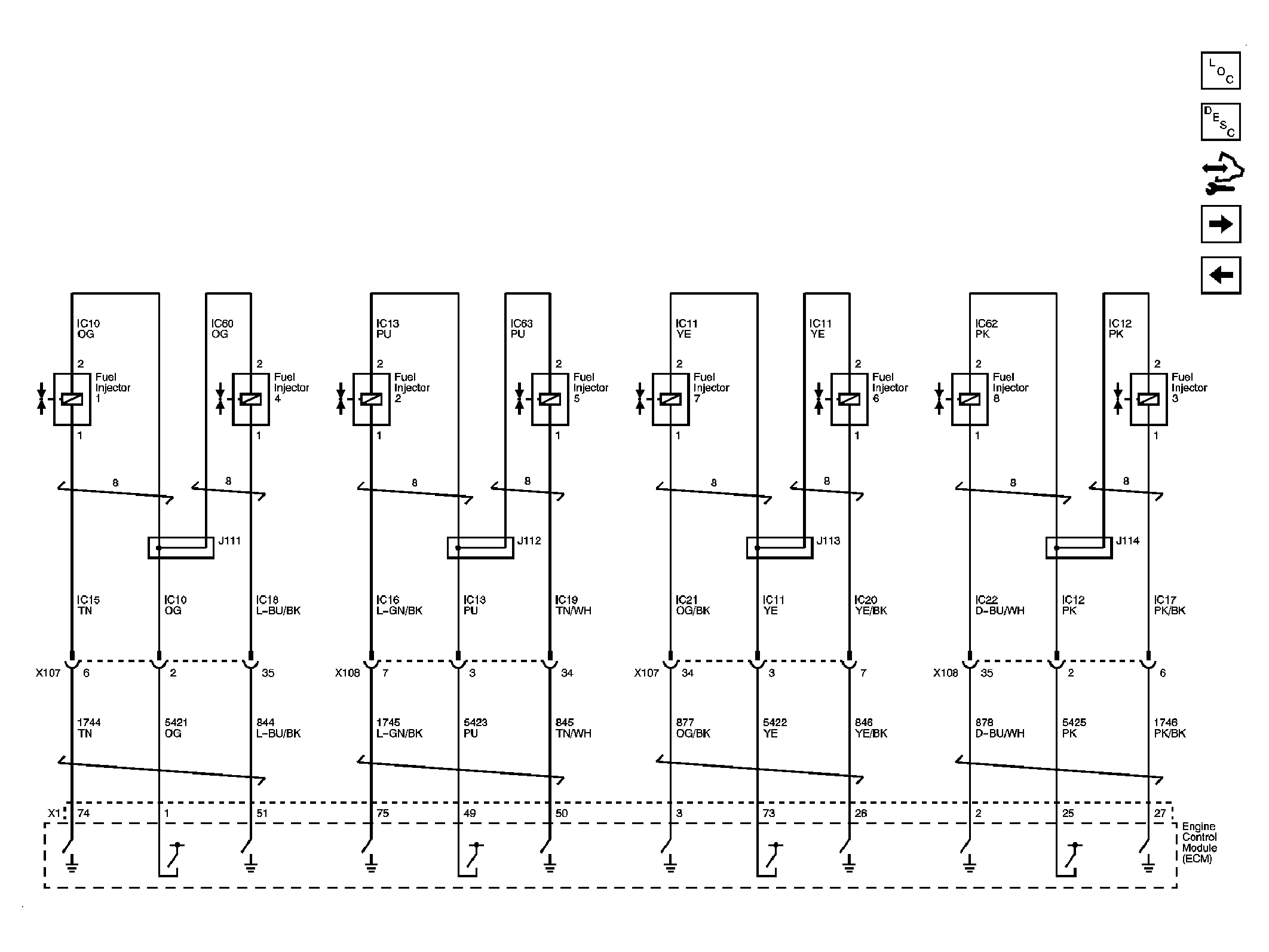
Fig 10: Fuel Controls - Fuel Injectors Schematic
GM1878828Courtesy of GENERAL MOTORS CORP.
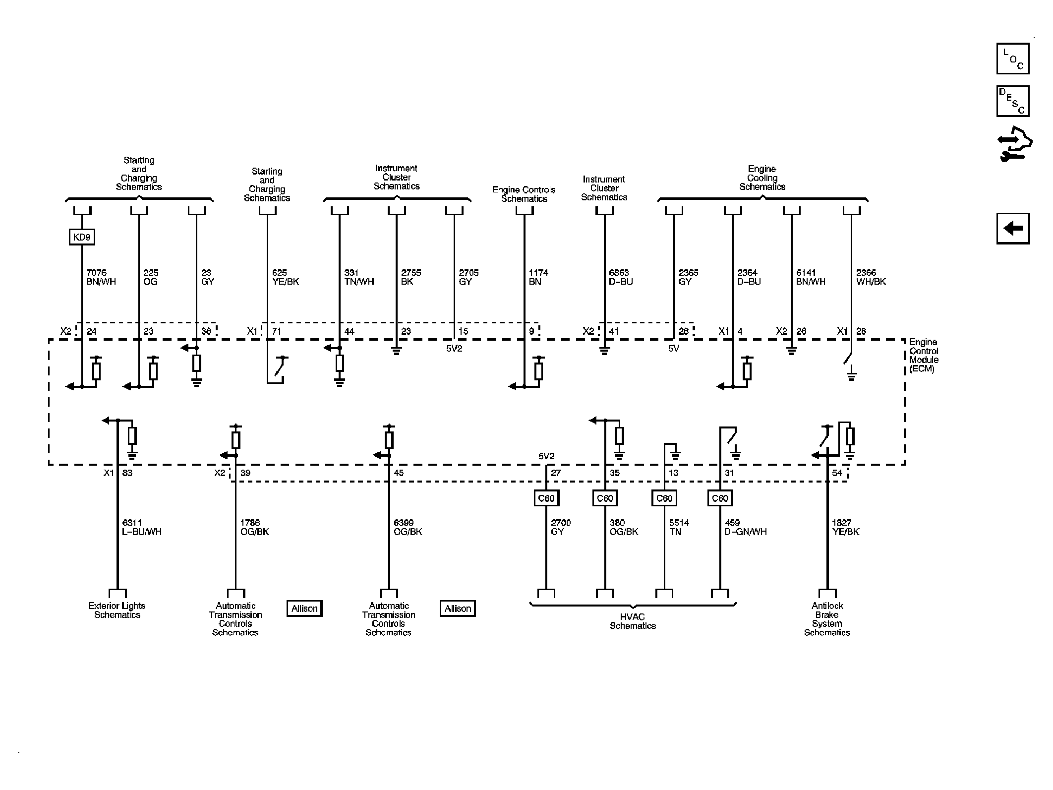
Fig 11: Controlled/Monitored Subsystem References Schematic
GM1878832Courtesy of GENERAL MOTORS CORP.