Test B: Power Sliding Door Closes And Reopens: Notes
- If door diagnostic system check has been performed, go to next step. If door diagnostic system check has not been performed, perform door diagnostic system check. See DOOR DIAGNOSTIC SYSTEM CHECK under SELF-DIAGNOSTIC SYSTEM.
- Close Power Sliding Door (PSD). Turn PSD on-off switch to ON position. Open PSD using a PSD OPEN/CLOSE switch. Close PSD using any PSD open-close switch. If PSD does not close and latch properly, go to next step. If PSD closes and latches properly, diagnose intermittent condition. See DIAGNOSING INTERMITTENTS in BODY CONTROL MODULES - MONTANA, SILHOUETTE & VENTURE article.
- Check door lock switch plate for proper door plunger operation and proper alignment of door plungers to "B" pillar contacts. If problem does not exist, go to next step. If problem exists, repair as necessary. After repair, go to step 19.
- Enter on-board diagnostic mode 2. See ENTERING DIAGNOSTIC MODES under SELF-DIAGNOSTIC SYSTEM. Manually open PSD. If sliding door alarm does not sound continuously, go to next step. If sliding door alarm sounds continuously, go to step 9.
- Position PSD at point where door plungers first make contact with "B" pillar switch plate pads. If sliding door alarm sounds continuously, go to next step. If sliding door alarm does not sound continuously, go to step 8.
- Slowly pull PSD closed to LATCH AJAR position. If sliding door alarms turns off, go to next step. If sliding door alarm does not turn off, go to step 14.
- Slowly push PSD to CLOSED/LATCHED position. If sliding door alarm sounds a short tone as door latches, go to DIAGNOSTIC AIDS . If sliding door alarm does not sound a short tone as door latches, go to step 15.
- Open PSD. Using a fused jumper wire connected to ground, backprobe "B" pillar switch plate harness connector terminals "E" and "F" (both Yellow wires). See Fig 1. If sliding door alarm sounds, go to step 10. If sliding door alarm does not sound, go to step 13.
- Check for short to ground in Yellow wire between "B" pillar switch plate pad and Rear Side Door Actuator Control Module (RSDACM). See WIRING DIAGRAMS . If problem does not exist, go to step 18. If problem exists, repair as necessary. After repair, go to step 19.
- Check for open or high resistance in Black wires between "B" pillar switch plate (terminals "C" and "D") and ground. See Fig 1. See WIRING DIAGRAMS . If problem does not exist, go to next step. If problem exists, repair as necessary. After repair, go to step 19.
- Check for open or high resistance in Yellow wire between PSD switch plate and PSD detent switch. If problem does not exist, go to next step. If problem exists, repair as necessary. After repair, go to step 19.
- Check for open or high resistance in Black wire between PSD switch plate and PSD detent switch. If problem does not exist, go to step 15. If problem exists, repair as necessary. After repair, go to step 19.
- Check for open or high resistance in yellow wire between "B" pillar switch plate pads and Rear Side Door Actuator Control Module (RSDACM). See WIRING DIAGRAMS . If problem does not exist, go to step 17. If problem exists, repair as necessary. After repair, go to step 19.
- Check for short to ground in Yellow wire between PSD switch plate pads and PSD detent switch. See WIRING DIAGRAMS . If problem does not exist, go to step 16. If problem exists, repair as necessary. After repair, go to step 19.
- Check PSD detent switch harness connector for poor connections or loose terminals. If problem does not exist, go to next step. If problem exists, repair as necessary. After repair, go to step 19.
- Replace PSD detent switch. After repair, go to step 19.
- Check RSDACM harness connectors for poor connections or loose terminals. If problem does not exist, go to next step. If problem exists, repair as necessary. After repair, go to step 19.
- Replace RSDACM. After repair, go to next step.
- Reinitialize PSD and operate system to verify repair. If problem does not exist, system is okay. If problem exists, go to step 3.
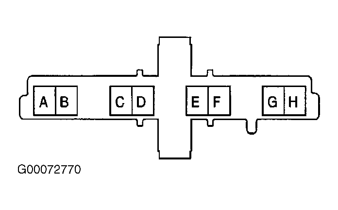 Courtesy of GENERAL MOTORS CORP.