Test G: Shock Sensor Inoperative
- If theft deterrent diagnostic system check has been performed, go to next step. If theft deterrent diagnostic system check has not been performed, perform THEFT DETERRENT DIAGNOSTIC SYSTEM CHECK
under SELF-DIAGNOSTIC SYSTEM.
- Arm Content Theft Deterrent (CTD) system. Tap on shock sensor. Shock sensor is located below instrument panel, next to steering column. If CTD system does not activate, go to next step. If CTD system activates, inspect for intermittents. See TROUBLE SHOOTING
.
- Disarm CTD system. Disconnect shock sensor harness connector. Connect a test light between shock sensor harness connector terminals "A" (Orange wire) and "C" (Black wire). See Fig 1
. If test light does not illuminate, go to next step. If test light illuminates, go to step 5
.
- Connect a test light between ground and shock sensor harness connector terminal "A" (Orange wire). If test light does not illuminate, go to step 6
. If test light illuminates, go to step 7
.
- Turn ignition switch to RUN position. Connect a test light between ground and shock sensor harness connector terminal "B" (Light Green wire). If test light does not illuminate, go to step 8
. If test light illuminates, go to step 9
.
- Inspect Orange wire for an open or short to ground between shock sensor harness connector terminal "A" and underhood junction block. If problem does not exist, go to step 9
. If problem exists, repair Orange wire as necessary. After repair, go to step 13
.
- Inspect Black wire for an open between ground and shock sensor harness connector terminal "C". Ground point is located behind right side of instrument panel, left of A/C-heater vent. If problem does not exist, go to step 9
. If problem exists, repair Black wire as necessary. After repair, go to step 13
.
- Turn ignition switch to OFF position. Inspect Light Green wire for an open or short to voltage between shock sensor harness connector terminal "B" and Body Control Module (BCM) harness connector C2 terminal D14. See Figure
and Fig 1
. If problem does not exist, go to step 10
. If problem exists, repair Light Green wire as necessary. After repair, go to step 13
.
- Inspect shock sensor harness connector for poor connections. If problem does not exist, go to step 11
. If problem exists, repair shock sensor harness connector as necessary. After repair, go to step 13
.
- Inspect BCM harness connector for poor connections. If problem does not exist, go to step 12
. If problem exists, repair BCM harness connector as necessary. After repair, go to step 13
.
- Replace shock sensor. After repair, go to step 13
.
- Replace BCM. Program BCM. See BODY CONTROL MODULE PROGRAMMING/REGULAR PRODUCTION OPTION CONFIGURATION under PROGRAMMING in BODY CONTROL MODULES - MONTANA, SILHOUETTE & VENTURE article. After repair, go to next step.
- Connect any harness connectors that may be still disconnected. Operate system to verify repair. If system is not operating correctly, repeat test beginning at step 2
.
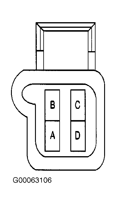 Courtesy of GENERAL MOTORS CORP.