Test A: Cruise Control Inoperative/Malfunctioning
- If cruise control diagnostic system check has been performed, go to next step. If cruise control diagnostic system check has not been performed, perform CRUISE CONTROL DIAGNOSTIC SYSTEM CHECK
.
- Turn ignition switch to OFF position. Disconnect Cruise Control Module (CCM) Black 10-pin harness connector. Turn ignition switch to RUN position. Connect a test light between ground and CCM harness connector terminal "F" (Pink wire). See Figure
. If test light illuminates, go to next step. If test light does not illuminate, go to step 36
.
- Connect test light between CCM harness connector terminals "E" (Black wire) and "F" (Pink wire). If test light illuminates, go to next step. If test light does not illuminate, go to step 37
.
- Turn cruise control functional switch to OFF position. Using test light connected to ground, probe CCM harness connector terminals "A" (Gray wire), "B" (Dark Blue wire) and "C" (Gray/Black wire). If test light does not illuminate at any terminal, go to next step. If test light illuminates at any terminal, go to step 16
.
- Turn ignition switch to RUN position. Turn cruise control functional switch to ON position. Connect test light between ground and CCM harness connector terminal "A" (Gray wire). If test light illuminates, go to next step. If test light does not illuminate, go to step 17
.
- Connect test light between ground and CCM harness connector terminal "B" (Dark Blue wire). Press and hold SET/COAST switch. If test light illuminates, go to next step. If test light does not illuminate, go to step 19
.
- Connect test light between ground and CCM harness connector terminal "C" (Gray/Black wire). Press and hold RESUME/ACCEL SWITCH. If test light illuminates, go to next step. If test light does not illuminate, go to step 20
.
- Connect test light between ground and CCM harness connector terminal "D" (Brown wire). If test light illuminates, leave test light connected and go to next step. If test light does not illuminate, go to step 21
.
- Depress brake pedal while observing test light. If test light does not illuminate, go to next step. If test light illuminates, go to step 22
.
- Connect test light between ground and CCM harness connector terminal "G" (White wire). If test light does not illuminate, leave test light connected and go to next step. If test light illuminates, go to step 23
.
- Depress brake pedal while observing test light. If test light illuminates, go to next step. If test light does not illuminate, go to step 24
.
- Using test light connected to battery voltage, probe CCM harness connector terminal "H" (Dark Green wire). If test light does not illuminate, leave test light connected and go to next step. If test light illuminates, go to step 25
.
- Connect scan tool to DLC. DLC is located below left side of instrument panel, to right of steering column. Command CRUISE INHIBIT/ENABLE OFF. If test light illuminates, go to next step. If test light does not illuminate, go to step 26
.
- Measure voltage between ground and CCM harness connector terminal "J" (White wire). If voltage is at or near battery voltage, go to next step. If voltage is not at or near battery voltage, go to step 27
.
- Raise and support vehicle so drive wheels may be rotated. Block one drive wheel. Set gear selector in Drive position. Verify speedometer operates properly. If speedometer does not operate properly, diagnose speedometer fault. See ANALOG INSTRUMENT PANELS - MONTANA, SILHOUETTE & VENTURE article. If speedometer operates properly, go to step 28
.
- Check wire(s) that caused test light to illuminate for short to voltage. If all wires are okay, go to step 34
. If any wire is shorted to voltage, repair appropriate wire(s) as necessary. After repair, go to step 43
.
- Check for open or high resistance in Gray wire between CCM harness connector terminal "A" and cruise control functional switches harness connector terminal A12. See Figure
and Fig 1
. Repair Gray wire as necessary. After repair, check system for normal operation. If Gray wire is okay, go to next step.
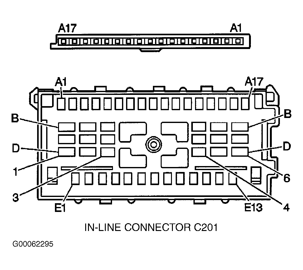 Courtesy of GENERAL MOTORS CORP.
- Check for open or high resistance in Pink wire between CCM harness connector terminal "F", cruise control functional switches terminal A13 and CRUISE fuse (10-amp) located in instrument panel fuse block. If Pink wire is okay, go to step 34
. If Pink wire is not okay, repair as necessary. After repair, go to step 43
.
- Check for open or high resistance in Dark Blue wire between CCM harness connector terminal "B" and cruise control functional switches harness connector terminal A14. See Figure
and Fig 1
. If Dark Blue wire is okay, go to step 34
. If Dark Blue wire is not okay, repair wire as necessary. After repair, go to step 43
.
- Check for open or high resistance in Gray/Black wire between CCM harness connector terminal "C" and cruise control functional switches harness connector terminal A15. See Figure
and Fig 1
. If Gray/Black wire is okay, go to step 35
. If Gray/Black wire is not okay, repair as necessary. After repair, go to step 43
.
- Check for open or high resistance Brown wire between cruise control release switch harness connector terminal "A" and cruise control module harness connector terminal "D". See Figure
and Fig 1
. If Brown wire is okay, go to step 29
. If Brown wire is not okay, repair as necessary. After repair, go to step 43
.
- Check for short to voltage in Brown wire between cruise control release switch harness connector terminal "A" and cruise control module harness connector terminal "D". See Figure
and Fig 1
. If Brown wire is okay, go to step 29
. If Brown wire is not okay, repair as necessary. After repair, go to step 43
.
- Check for short to voltage in White wire between brakelight switch harness connector terminal "B" and CCM harness connector terminal "G". See Figure
and Fig 1
. If White wire is okay, go to step 30
. If White wire is not okay, repair as necessary. After repair, go to step 43
.
- Check for open or high resistance in White wire between brakelight switch harness connector terminal "B" and CCM harness connector terminal "G". See Figure
and Fig 1
. If White wire is okay, go to step 30
. If White wire is not okay, repair as necessary. After repair, go to step 43
.
- Check for short to ground in Dark Green wire between CCM harness connector terminal "H" and PCM harness connector C1 terminal No. 72. See Figure
and Figure
. If Dark Green wire is okay, go to step 33
. If Dark Green wire is not okay, repair as necessary. After repair, go to step 43
.
- Check for open, high resistance or short to voltage Dark Green wire between CCM harness connector terminal "H" and PCM harness connector C1 terminal No. 72. See Figure
and Figure
. If Dark Green wire is okay, go to step 33
. If Dark Green wire is not okay, repair as necessary. After repair, go to step 43
.
- Check for open, high resistance or short to voltage in White wire between CCM harness connector terminal "J" and PCM harness connector C2 terminal No. 59. See Figure
and Figure
. If White wire is okay, go to step 33
. If White wire is not okay, repair as necessary. After repair, go to step 43
.
- Check for open or high resistance in Dark Green wire between CCM harness connector terminal "K" and PCM harness connector C1 terminal No. 55. See Figure
and Figure
. If wire is okay, go to step 33
. If Dark Green wire is not okay, repair as necessary. After repair, go to step 43
.
- Check cruise control release switch for proper adjustment. See CRUISE CONTROL RELEASE & BRAKELIGHT SWITCHES
under ADJUSTMENTS. Adjust as necessary. After repair, go to step 43
. If adjustment is okay, go to step 31
.
- Check brakelight switch for proper adjustment. See CRUISE CONTROL RELEASE & BRAKELIGHT SWITCHES
under ADJUSTMENTS. Adjust as necessary. After repair, go to step 43
. If adjustment is okay, go to step 32
.
- Check cruise control release switch harness connector for poor terminal contact or damage. Repair or replace as necessary. After repair, go to step 43
. If terminal contact is okay, go to step 38
.
- Check brakelight switch harness connector for poor terminal contact or damage. Repair or replace as necessary. After repair, go to step 43
. If terminal contact is okay, go to step 39
.
- Check PCM harness connector for poor terminal contact or damage. Repair or replace as necessary. After repair, go to step 43
. If terminal contact is okay, go to step 40
- Check cruise control functional switches harness connector for poor terminal contact or damage. Repair or replace as necessary. After repair, go to step 43
. If terminal contact is okay, go to step 41
.
- Check CCM harness connector for poor terminal contact or damage. Repair or replace as necessary. After repair, go to step 43
. If terminal contact is okay, go to step 42
.
- Repair Pink wire as necessary between CCM harness connector terminal "F" and CRUISE fuse (10-amp) in instrument panel fuse block. After repair, go to step 43
.
- Repair Black wire between CCM harness connector terminal "E" and chassis ground. Ground point G202 is located behind left side of dash, on underside of cross car beam. See Figure
. After repair, go to step 43
.
- Replace cruise control release switch. See CRUISE CONTROL RELEASE & BRAKELIGHT SWITCHES
under REMOVAL & INSTALLATION. After repair, go to step 43
.
- Replace brakelight switch. See CRUISE CONTROL RELEASE & BRAKELIGHT SWITCHES
under REMOVAL & INSTALLATION. After repair, go to step 43
.
- Replace PCM. See POWERTRAIN CONTROL MODULE
under REMOVAL & INSTALLATION. Program PCM as necessary. See PROGRAMMING in BODY CONTROL MODULES - MONTANA, SILHOUETTE & VENTURE article. After repair, go to step 43
.
- Replace cruise control functional switches. See CRUISE CONTROL FUNCTIONAL SWITCHES
under REMOVAL & INSTALLATION. After repair, go to step 43
.
- Replace CCM. See CRUISE CONTROL MODULE
under REMOVAL & INSTALLATION. After repair, go to next step .
- Operate vehicle to verify fault(s) no longer exist. If cruise control system does not operate properly, go to step 2
.