Installation Procedure
 Courtesy of GENERAL MOTORS CORP.
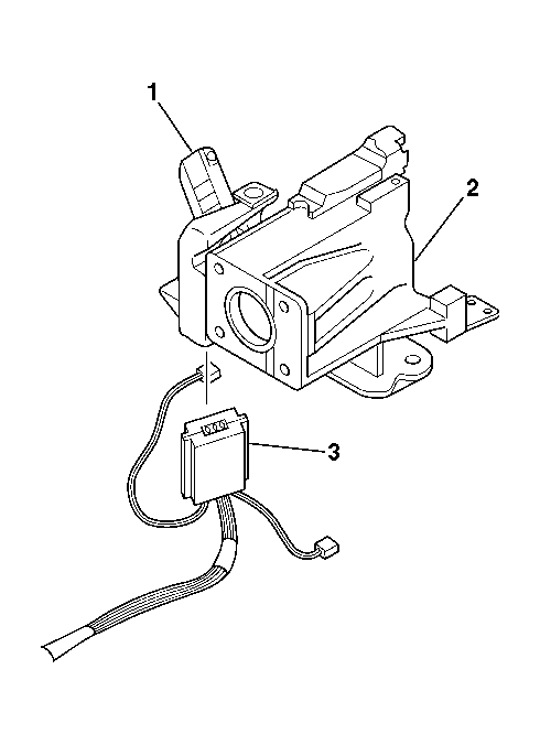
- Install the ignition switch (3) to the lock module (1).
 Courtesy of GENERAL MOTORS CORP.
- Install the key alarm connector (1) into the lock module assembly (2).
- Push the key alarm connector (1) into the lock module assembly (2).
- Rotate the key alarm connector (1) 90 degrees so that the key alarm connector (1) locks into place.
- Install the passkey connector into the lock module assembly (2).
 Courtesy of GENERAL MOTORS CORP.
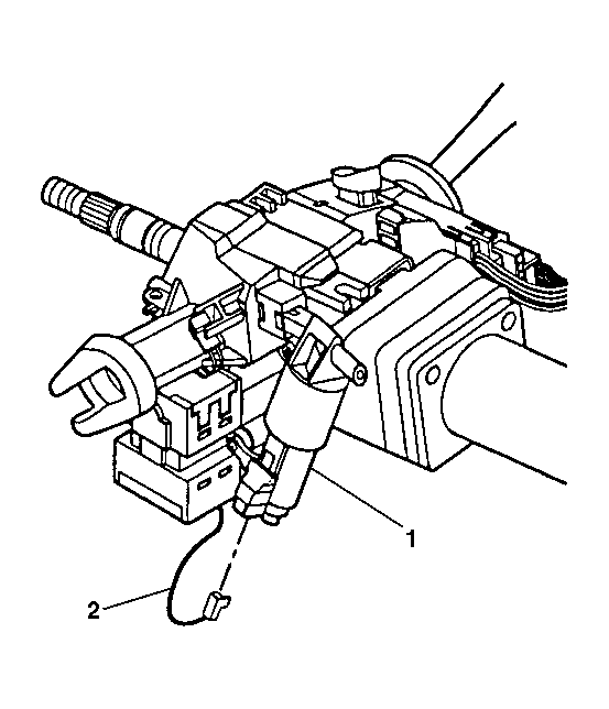
- Install the connector (2) to the electric park lock (1), for vehicles equipped with floor shifters.
 Courtesy of GENERAL MOTORS CORP.
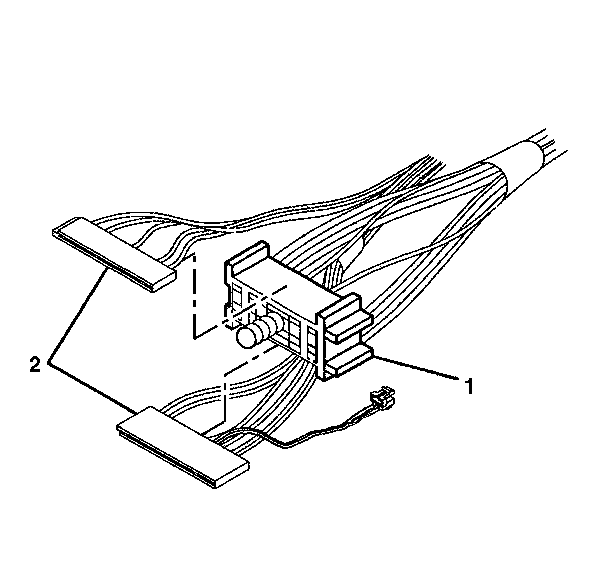
- Slide the 2 connectors (2) of the turn signal and multifunction switch into the bulkhead connector (1).
 Courtesy of GENERAL MOTORS CORP.
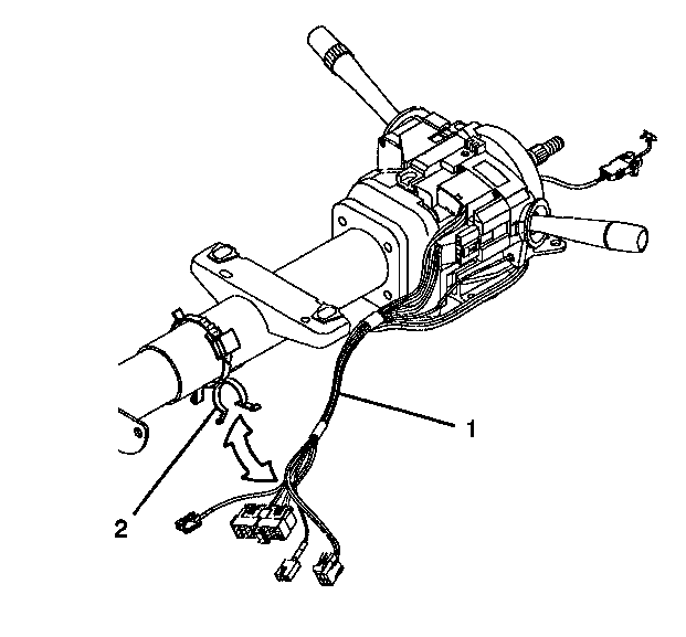
- Attach the wire harness assembly (1) to the steering column wire harness strap (2).
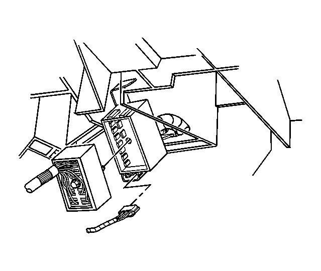 Courtesy of GENERAL MOTORS CORP.
- Connect the steering column electrical connectors to the vehicle.
- Install the trim covers to the column. Refer to Steering Column Trim Covers Replacement - On Vehicle .
- Install the knee bolster. Refer to KNEE BOLSTER REPLACEMENT (NON-LUXURY)
or KNEE BOLSTER REPLACEMENT (LUXURY)
in Instrument, Panel, Gauges and Console.
- Enable the SIR system. Refer to ACTIVATING SYSTEM
in SIR.
- It may be necessary to reprogram the theft deterrent system if the module was replaced. Refer to PROGRAMMING THEFT DETERRENT SYSTEM COMPONENTS
in Theft Deterrent.