Test K: Memory Seat Feature Inoperative
- If power seat system diagnostic system check has been performed, go to next step. If power seat system diagnostic system check has not been performed, perform POWER SEAT SYSTEMS DIAGNOSTIC SYSTEM CHECK
under SELF-DIAGNOSTIC SYSTEM.
- Operate memory seats to verify customer concern. If memory seats does not operate, go to next step. If memory seats operates, inspect for intermittents. See TROUBLE SHOOTING
.
- Connect scan tool to Data Link Connector (DLC). DLC is located below left side of instrument panel, on hood release bracket. Turn ignition switch to RUN position. Using scan tool, observe memory recall switches parameter in Memory Mirror Module (MMM) data list. Press MEMORY 1 button on memory function switch. If scan tool displays memory 1, go to next step. If scan tool does not display memory 1, go to step 7
.
- Using scan tool, observe memory recall switches parameter. Press MEMORY 2 button on memory function switch. If scan tool displays memory 2, go to next step. If scan tool does not display memory 2, go to step 9
.
- Using scan tool, observe memory recall switches parameter. Press SET button on memory function switch. If scan tool displays SET, go to next step. If scan tool does not display SET, go to step 10
.
- Using scan tool, observe memory recall switches parameter. Press EXIT button on memory function switch. If scan tool does not display EXIT, go to step 11
. If scan tool displays EXIT, go to step 16
.
- Disconnect memory function switch 5-pin harness connector. Connect a 3-amp fused jumper wire between ground and memory function switch harness connector terminal "A" (White wire). See Figure
. Using scan tool, observe memory recall switches parameter. If scan tool displays memory 1, go to next step. If scan tool does not display memory 1, go to step 12
.
- Connect a 3-amp fused jumper wire between memory function switch harness connector terminals "A" (White wire) and "E" (Black wire). See Figure
. Using scan tool, observe memory recall switches parameter. If scan tool displays memory 1, go to step 19
. If scan tool does not display memory 1, go to step 21
.
- Disconnect memory function switch 5-pin harness connector. Connect a 3-amp fused jumper wire between ground and memory function switch harness connector terminal "C" (Purple wire). See Figure
. Using scan tool, observe memory recall switches parameter. If scan too does not display memory 2, go to step 13
. If scan tool displays memory 2, go to step 19
.
- Disconnect memory function switch 5-pin harness connector Connect a 3-amp fused jumper wire between ground and memory function switch harness connector terminal "B" (Orange wire). See Figure
. Using scan tool, observe memory recall switches parameter. If scan tool does not display SET, go to step 14
. If scan tool displays SET, go to step 19
.
- Disconnect memory function switch 5-pin harness connector Connect a 3-amp fused jumper wire between ground and memory function switch harness connector terminal "D" (Black wire). See Figure
. Using scan tool, observe memory recall switches parameter. If scan tool does not display EXIT, go to step 15
. If scan tool displays EXIT, go to step 19
.
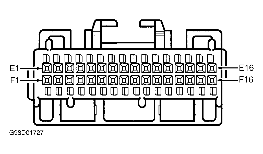
- Inspect White wire for an open between memory function switch harness connector terminal "A" and MMM harness connector terminal E2. See Figure
and Fig 1
. If problem does not exist, go to step 18
. If problem exists, repair White wire as necessary. After repair, go to step 25
.
- Inspect Purple wire for an open between memory function switch harness connector terminal "C" and MMM harness connector terminal F2. See Figure
and Fig 1
. If problem does not exist, go to step 18
. If problem exists, repair Purple wire as necessary. After repair, go to step 25
.
- Inspect Orange wire for an open between memory function switch harness connector terminal "B" and MMM harness connector terminal E3. See Figure
and Fig 1
. If problem does not exist, go to step 18
. If problem exists, repair Orange wire as necessary. After repair, go to step 25
.
- Inspect Black wire for an open between memory function switch harness connector terminal "D" and MMM harness connector terminal F3. See Figure
and Fig 1
. If problem does not exist, go to step 18
. If problem exists, repair Black wire as necessary. After repair, go to step 25
.
- Inspect low reference circuit for an open between MSM harness connector C1 terminal No. 12 and suspect seat position sensor. See POSITION SENSOR CIRCUIT IDENTIFICATION
. See Figure
and Figure
. If problem does not exist, go to next step. If problem exists, repair low reference circuit as necessary. After repair, go to step 25
.
- Inspect 5-volt reference circuit for an open between MSM harness connector C1 terminal No. 13 and suspect seat position sensor. See POSITION SENSOR CIRCUIT IDENTIFICATION
. See Figure
and Figure
. If problem does not exist, go to step 20
. If problem exists, repair 5-volt reference circuit as necessary. After repair, go to step 25
.
- Inspect MMM harness connector for poor connections. If problem does not exist, go to step 22
. If problem exists, repair MMM harness connector as necessary. After repair, go to step 25
.
- Inspect memory function switch harness connector for poor connections. If problem does not exist, go to step 23
. If problem exists, repair memory function switch harness connector as necessary. After repair, go to step 25
.
- Inspect MSM harness connector for poor connections. If problem does not exist, go to step 24
. If problem exists, repair MSM harness connector as necessary. After repair, go to step 25
.
- Repair open in Black wire between ground and memory function switch. Ground point is located behind left kick panel. After repair, go to step 25
.
- Replace MMM, then go to step 25
.
- Replace memory function switch, then go to step 25
.
- Replace MSM, then go to next step.
- Operate system to verify repair. If system is not operating correctly, repeat test beginning at step 2
.
 Courtesy of GENERAL MOTORS CORP.