DTC B2472: Low Beam Fault: Testing
- If lighting system diagnostic system check has been performed, go to next step. If lighting system has not been performed, go to LIGHTING SYSTEM DIAGNOSTIC SYSTEM CHECK
under SELF-DIAGNOSTIC SYSTEM.
- Connect scan tool to Data Link Connector (DLC). Turn ignition on. Turn headlight switch off. Using scan tool, select BCM TEST, LIGHTS, LOW BEAM. Using scan tool, turn low beams on and off. If headlights are off, go to next step. If headlights come on, go to step 4
.
- Turn headlight switch on. If headlights come on, go to step 5
. If headlights do not come on, go to step 6
.
- Disconnect White 16-pin connector C201 (body-to-instrument panel wiring harness, located behind left side of instrument panel, below headlight switch). Using scan tool, turn low beams off. If headlights are off, go to step 7
. If headlights are on, go to step 8
.
- Cycle ignition. If DTC B2472 is current, go to step 11
. If DTC B2472 is now history, go to step 12
.
- Check for open in Yellow wire between headlight relay and White 16-pin connector C201 (body-to-instrument panel wiring harness, located behind left side of instrument panel, below headlight switch). If circuit is okay, go to step 16
. If faulty circuit is found, go to step 17
.
- Disconnect headlight switch connectors. Using DVOM, measure resistance between headlight switch Black 12-pin connector C1 terminal "C" (Yellow wire) and ground. See Fig 1
. If resistance is 5 ohms or less, go to step 9
. If resistance is greater than 5 ohms, go to step 10
.
- Check for short to ground in Yellow wire between PZM, headlight relay, headlight switch and IPC. See HEADLIGHT SYSTEMS & DAYTIME RUNNING LIGHTS article. If circuit is okay, go to step 13
. If faulty circuit is found, go to step 17
.
- Check for short to ground in Yellow wire between PZM, headlight relay, headlight switch and IPC. See HEADLIGHT SYSTEMS & DAYTIME RUNNING LIGHTS article. If circuit is okay, go to step 14
. If faulty circuit is found, go to step 17
.
- Replace headlight switch. See HEADLIGHT SWITCH
under REMOVAL & INSTALLATION. After repairs, go to step 18
.
- Check for open in Yellow wire between PZM, headlight relay, headlight switch and IPC. See HEADLIGHT SYSTEMS & DAYTIME RUNNING LIGHTS article. If circuit is okay, go to step 15
. If faulty circuit is found, go to step 17
.
- Repair intermittent short to battery in Yellow wire between PZM, headlight relay, headlight switch and IPC. After repairs, go to step 18
.
- Replace the headlight relay. After repairs, go to step 18
.
- Replace IPC. See ANALOG INSTRUMENT PANELS - ELDORADO article. After repairs, go to step 18
.
- Replace PZM. See PLATFORM ZONE MODULE (PZM)
under REMOVAL & INSTALLATION. After repairs, go to step 18
.
- Check for open in White wire between PZM connector C2 terminal C16 and headlight relay. See Figure
. If faulty circuit is found, go to step 13
. If circuit is okay, go to next step.
- Repair open or short to ground in Yellow wire. After repairs, go to next step.
- Use scan tool to clear DTCs. Recheck system operation. Recheck for DTCs. If DTC resets, go to step 2
. If DTC does not reset, repair is complete.
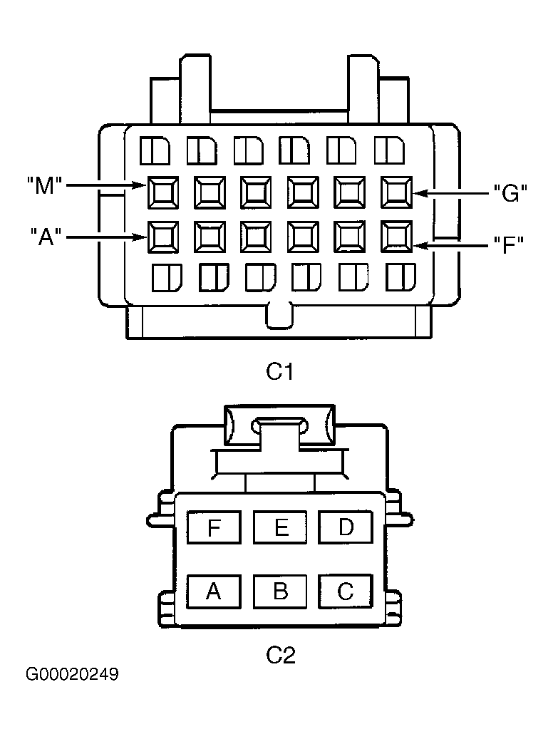 Courtesy of GENERAL MOTORS CORP.