Installation Procedure
 Courtesy of GENERAL MOTORS CORP.
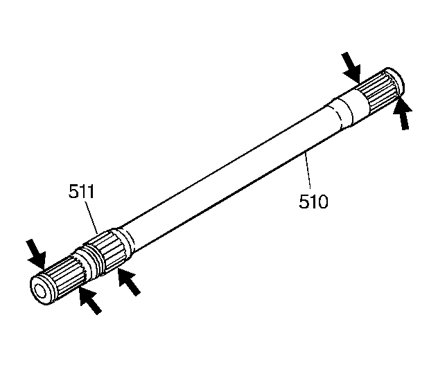
- Inspect the output shaft (510) and the bearing (511) for the following:
- A cracked or deformed bearing cage
- Damaged bushing journals
- Stripped splines
- A damaged retainer ring groove
 Courtesy of GENERAL MOTORS CORP.
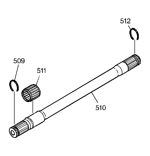
- Install the drive axle retaining ring (509) and the output shaft differential inboard snap ring (512) onto the output shaft (510).
- Install the fourth clutch bearing (511) onto the output shaft (510).
 Courtesy of GENERAL MOTORS CORP.
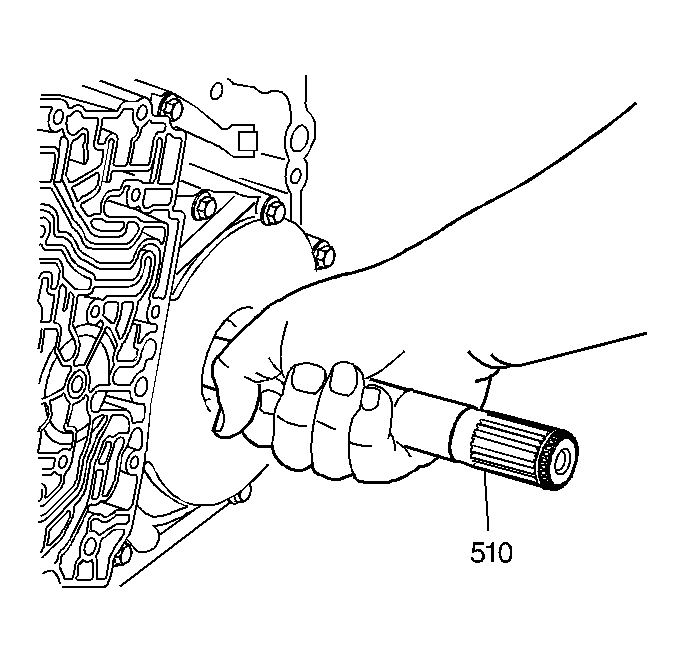
- Hold the front differential carrier in place and carefully install the output shaft (510) into the transmission through the left wheel opening. Extend the output shaft through the differential side gear.
- Install the case extension housing. Refer to Case Extension Housing Replacement .
- Connect the left drive axle to the transaxle. Refer to Wheel Drive Shaft Replacement
in Wheel Drive Shafts.
- Fill the transaxle to the proper level. Refer to Fluid Capacity Specifications .
- Inspect the transaxle fluid level. Refer to Transmission Fluid Checking Procedure
.
- Inspect for fluid leaks.