Control Module Input/Output Test
- Perform the following test if headlights do not turn on or off manually.
- Unplug lamp control module harness connector C2. See TWILIGHT SENTINEL CONTROL MODULE
under REMOVAL & INSTALLATION. It is normal for chime to sound when module is disconnected and driver door is open. Ensure connector terminals make positive contact.
- Turn ignition off. Measure resistance between harness connector C2 terminal A5 (Light Blue wire) and ground. See Fig 1
and Fig 2
. Resistance should be infinite with headlight switch in OFF position. With headlight switch in ON position, resistance should be less than 5 ohms.
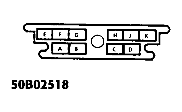 Courtesy of GENERAL MOTORS CORP.
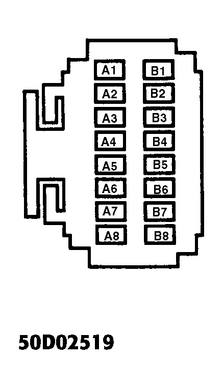 Courtesy of GENERAL MOTORS CORP.
- If resistance is not as specified, check Black/White wire from headlight switch to ground, or White wire between headlight switch and twilight sentinel control module. For wiring diagrams See appropriate WIRING DIAGRAMS
article.
- If both circuits are okay, check headlight switch connector terminals for positive contact. If terminal connections are good, replace headlight switch. See HEADLIGHT/TWILIGHT SENTINEL SWITCH
under REMOVAL & INSTALLATION.
- Turn ignition on. Set gear selector to "P" position. Backprobe twilight sentinel control module harness connector C2 terminal B8 (Light Green wire). If battery voltage does not exist, check for open or short to ground in Light Green/Black wire between module harness connector C2 terminal B8 and neutral safety switch.
- Ensure neutral safety switch harness connector terminals are secure. Check instrument panel fuse 1B. If terminals and fuse are okay, adjust or replace neutral safety switch, on top of transmission.