Test J - Pump Motor Circuit
- Perform ABS/TCS functional check before proceeding. See Figure
. Turn ignition off. Connect Tech 1 scan tester to DLC connector. Turn ignition switch to RUN position.
- Use scan tester to bleed Pressure Modulator Valve (PMV). If pump motor runs, turn ignition off. Disconnect scan tester, and go to step 9).
- If pump motor does not run, clear codes. Turn ignition off. Disconnect scan tester, and go to next step.
- With ignition off, disconnect ABS pump relay. Turn ignition switch to RUN position. Measure voltage between ground and ABS pump relay connector terminal No. 85. See Figure
. Battery voltage should be present. If battery voltage is not present, check and repair open in circuit No. 1633 (Red wire).
- Measure voltage between ground and ABS pump relay connector terminal No. 30. Battery voltage should be present. If battery voltage is not present, check fuse No. 1 in left underhood fuse block. Check circuits No. 642 (Red wire) and No. 864 for short to ground. If circuit No. 864 (Red wire) was shorted to ground, replace ABS pump relay after circuit is repaired.
- Connect a fused jumper wire between ABS pump relay connector terminals No. 30 and 87. Pump motor should run. If motor does not run, go to next step. If motor runs, reconnect ABS pump relay, and go to step 11).
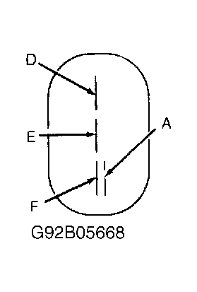
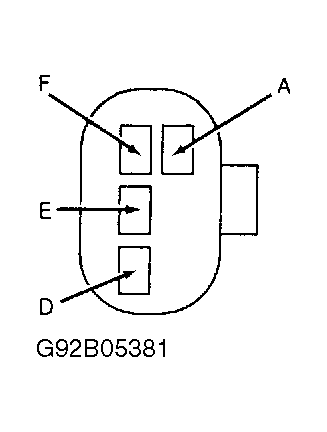
- Turn ignition off. Disconnect Pressure Modulator Valve (PMV) C2 connector (Gray). Measure voltage between ground and PMV C2 connector terminal "A". See Fig 1
or Fig 2
. Battery voltage should be present with fused jumper wire connected between ABS pump relay connector terminals No. 30 and 87. If battery voltage is not present, check and repair circuit No. 864 (Red wire).
- Measure voltage between PMV C2 connector terminals "A" (+) and "E" ( - ). Battery voltage should be present. If battery voltage is not present, check for open in circuit No. 1150 (Black wire). If battery voltage is present, replace PMV assembly.
- Measure resistance between PMV assembly terminal "D" and PMV casing. See Fig 1
or Fig 2
. Resistance should be infinite. If resistance is not as specified, replace PMV assembly.
- Measure resistance between PMV assembly terminals "D" and "F". Resistance should be 10-40 ohms. If resistance is not as specified, replace PMV assembly. If resistance is as specified, reconnect PMV connector, and go to next step.
- Turn ignition off. Disconnect EBCM/EBTCM connector. Connect Pinout Box (J-38716). Measure resistance between ground and pinout box pin No. 1. See Figure
. Resistance should be less than 5 ohms. If resistance is not as specified, check and repair open in circuit No. 251 (Black/White wire).
- Connect a fused jumper wire between pinout box pins No. 1 and 34. See Figure
. Connect a second fused jumper wire between pinout box pins No. 1 and 15. Pump motor should run. If motor does not run, check and repair open in circuit No. 854 (Pink wire). If Pink wire is okay, replace ABS pump relay. If pump motor runs, remove jumper wires and turn ignition off.
- Measure resistance between pinout box pins No. 1 and 31. See Figure
. Resistance should be more than 5 ohms. If resistance is not as specified, check and repair short to ground in circuit No. 1292 (Light Green/Black wire) and circuit No. 1293 (Light Blue/Black wire).
- Measure resistance between pinout box pins No. 31 and 49. See Figure
. Resistance should be 10-40 ohms. If high resistance is measured, check for open in circuits No. 1292 (Light Green/Black wire) and No. 1293 (Light Blue/Black wire). Check PMV harness connector for proper terminal contact. If low resistance is measured, check for short in circuits No. 1292 (Light Green/Black wire) and No. 1293 (Light Blue/Black wire).
- If all readings are within specification, check EBCM/EBTCM connector terminals for poor contact. If connector terminals are okay, replace EBCM/EBTCM. After all repairs are complete, clear codes, and repeat ABS/TCS functional check. See Figure
.
 Courtesy of GENERAL MOTORS CORP.
 Courtesy of GENERAL MOTORS CORP.