88-Pin Transmission Control Module (1996)
NOTE:
TCM harness connector can be removed after ignition switch has been turned to OFF position, for 30 seconds. By removing TCM connector, battery voltage is disconnected and DTC memory is erased.
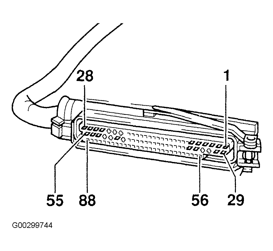
Turn ignition switch to OFF position. Remove TCM. Disconnect TCM harness connector. Connect VAG 1598/20 test box to TCM harness connector.
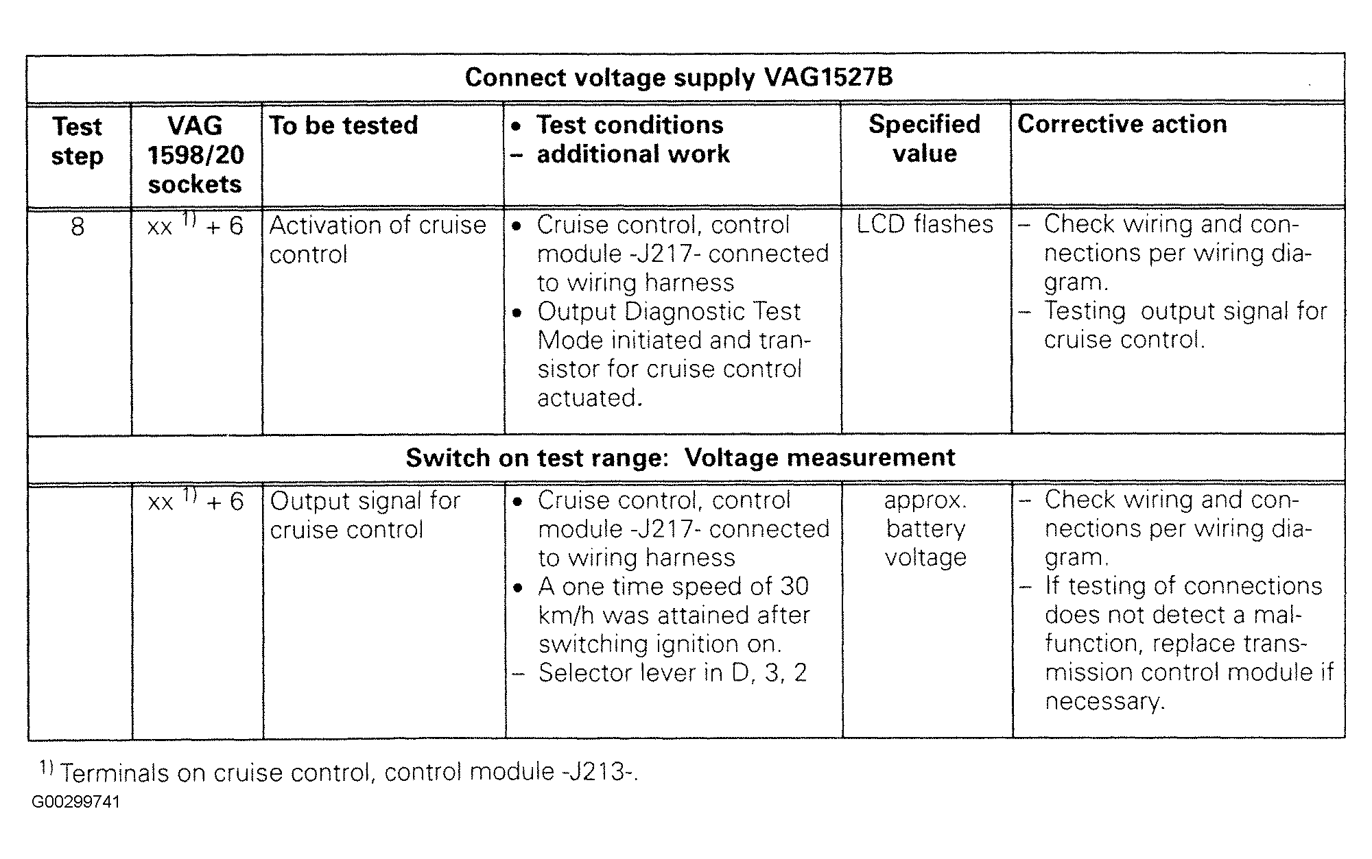
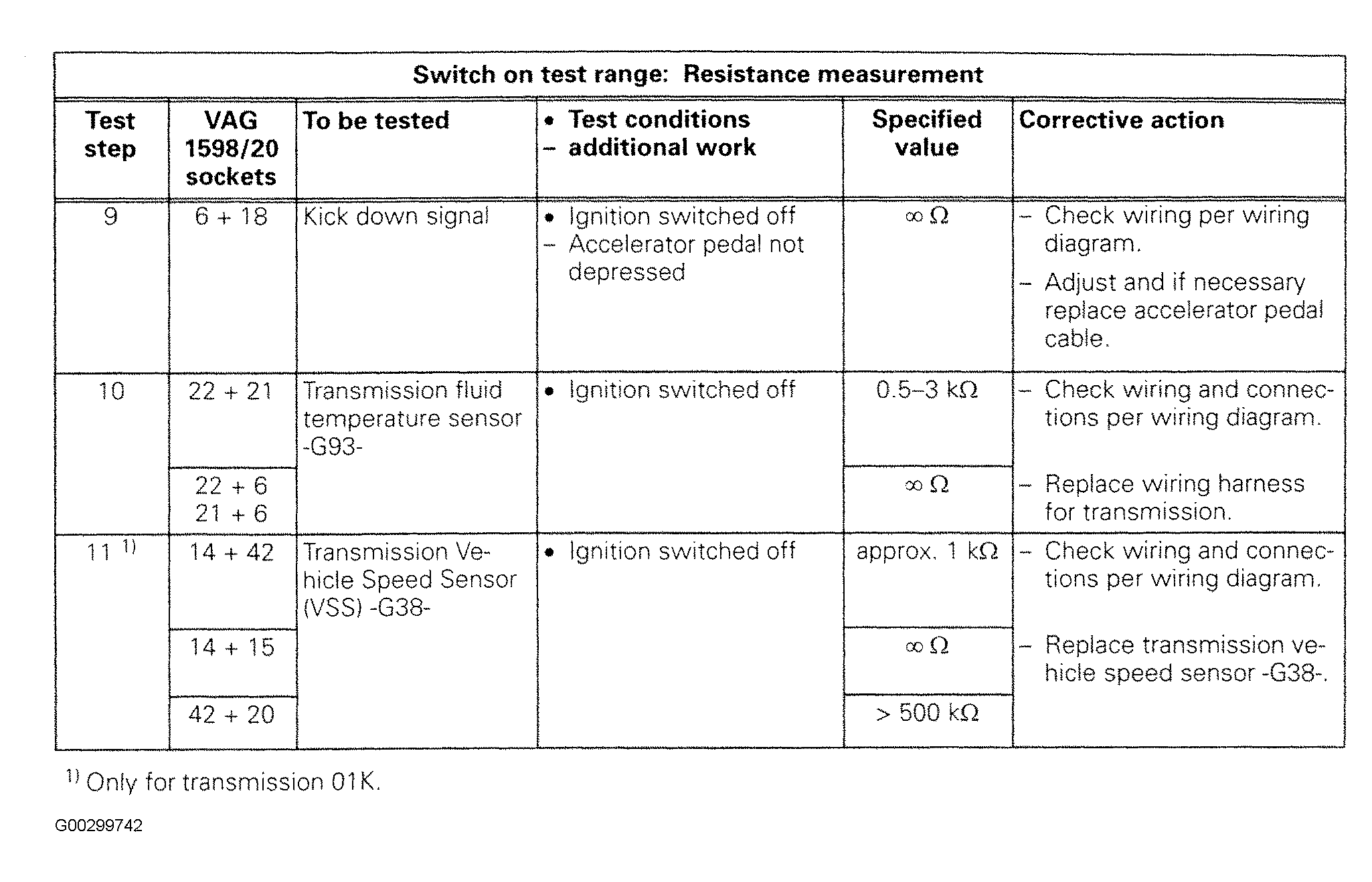
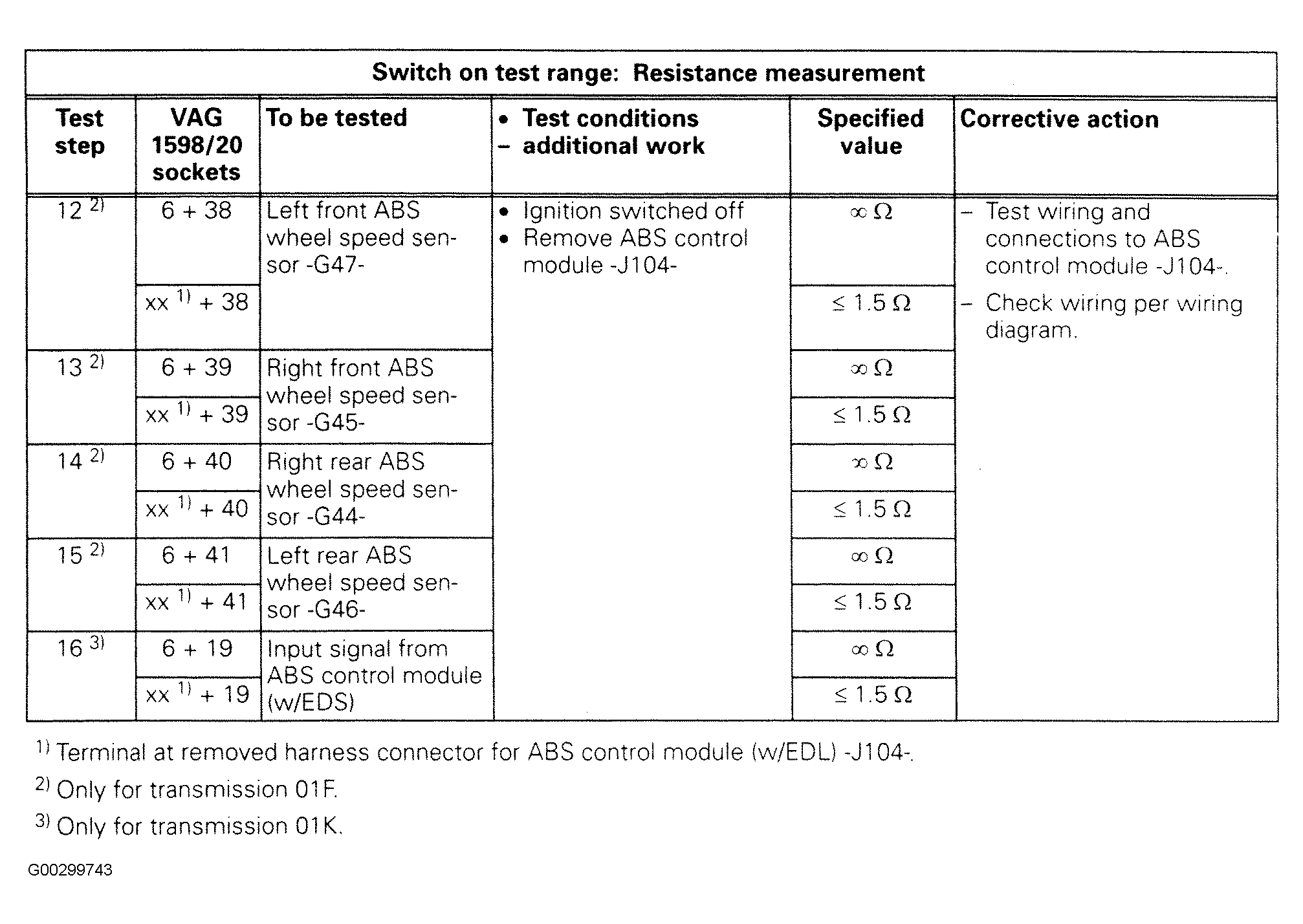
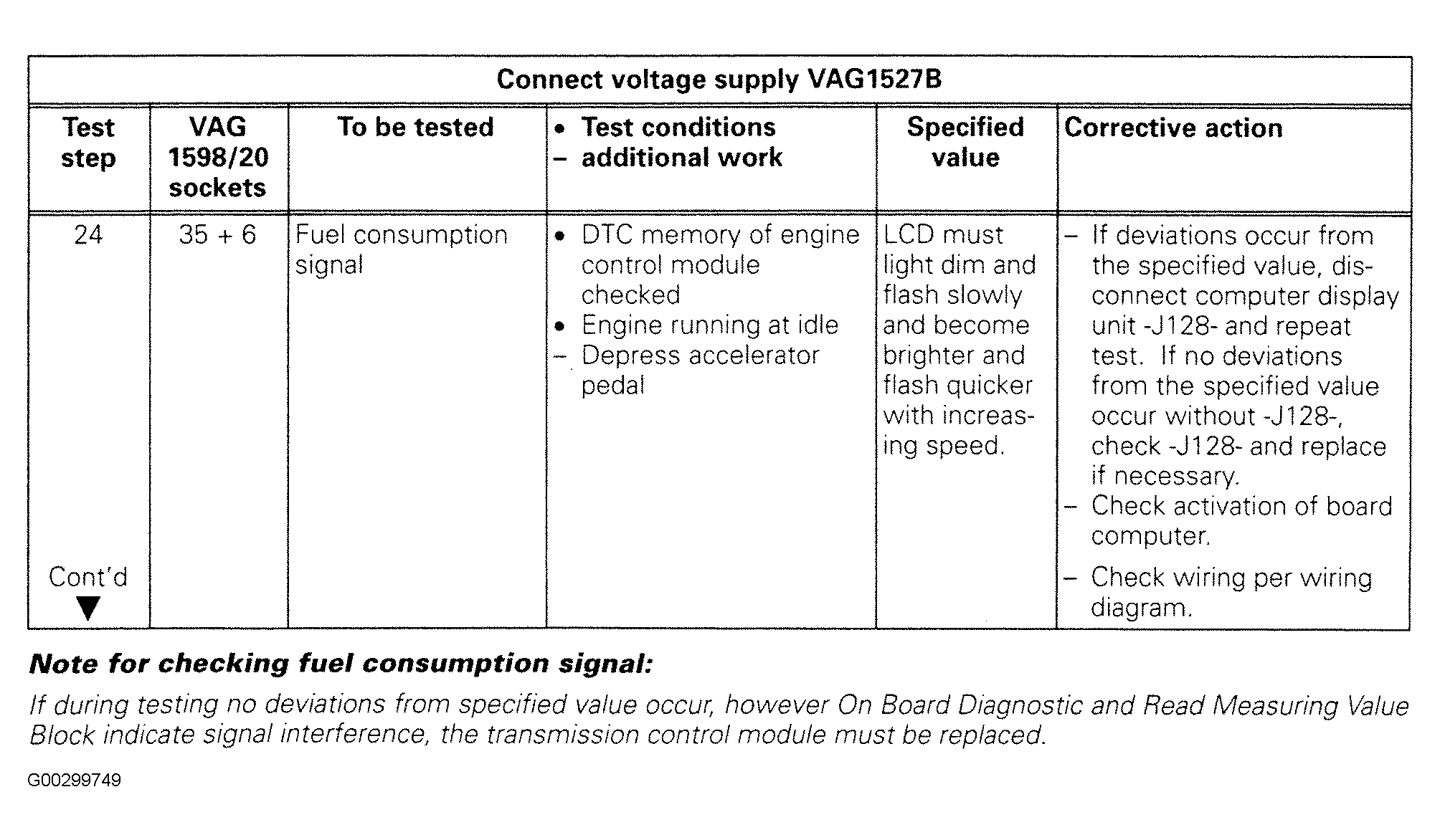
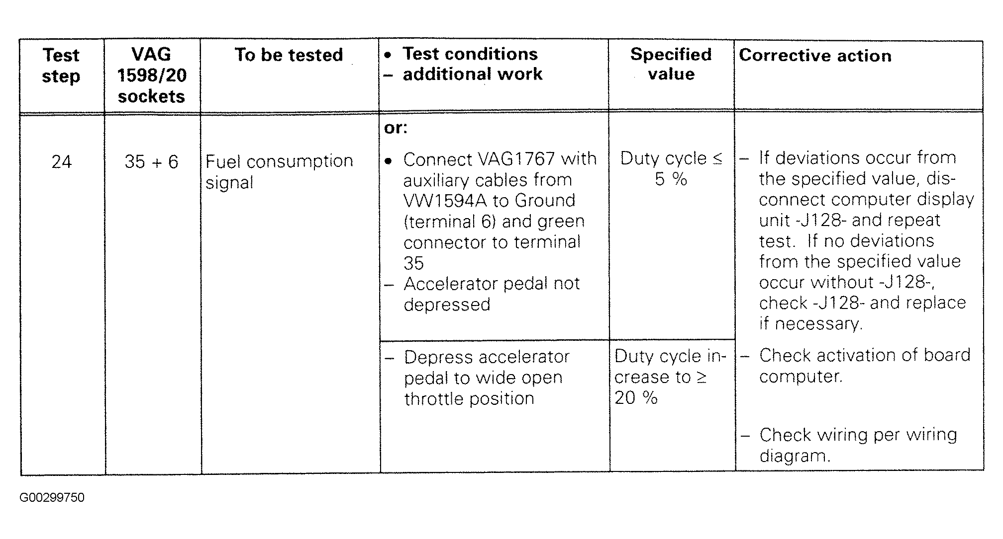
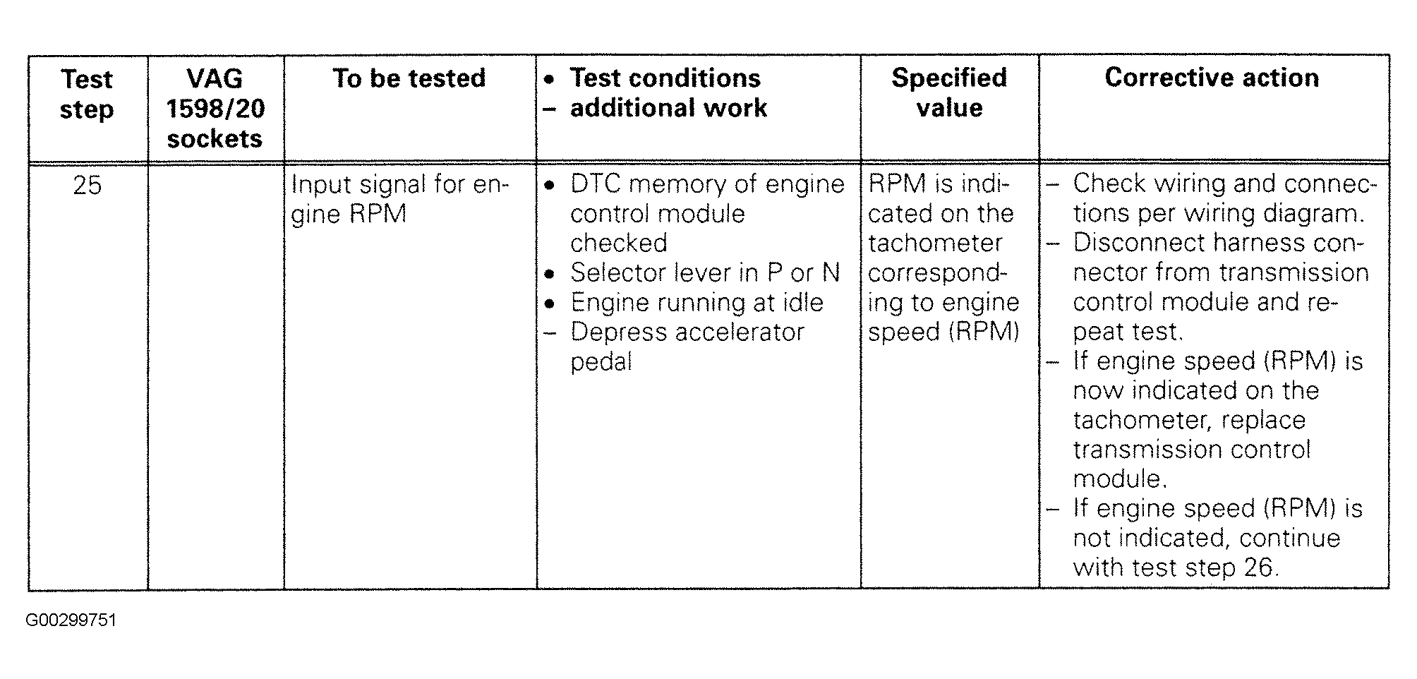
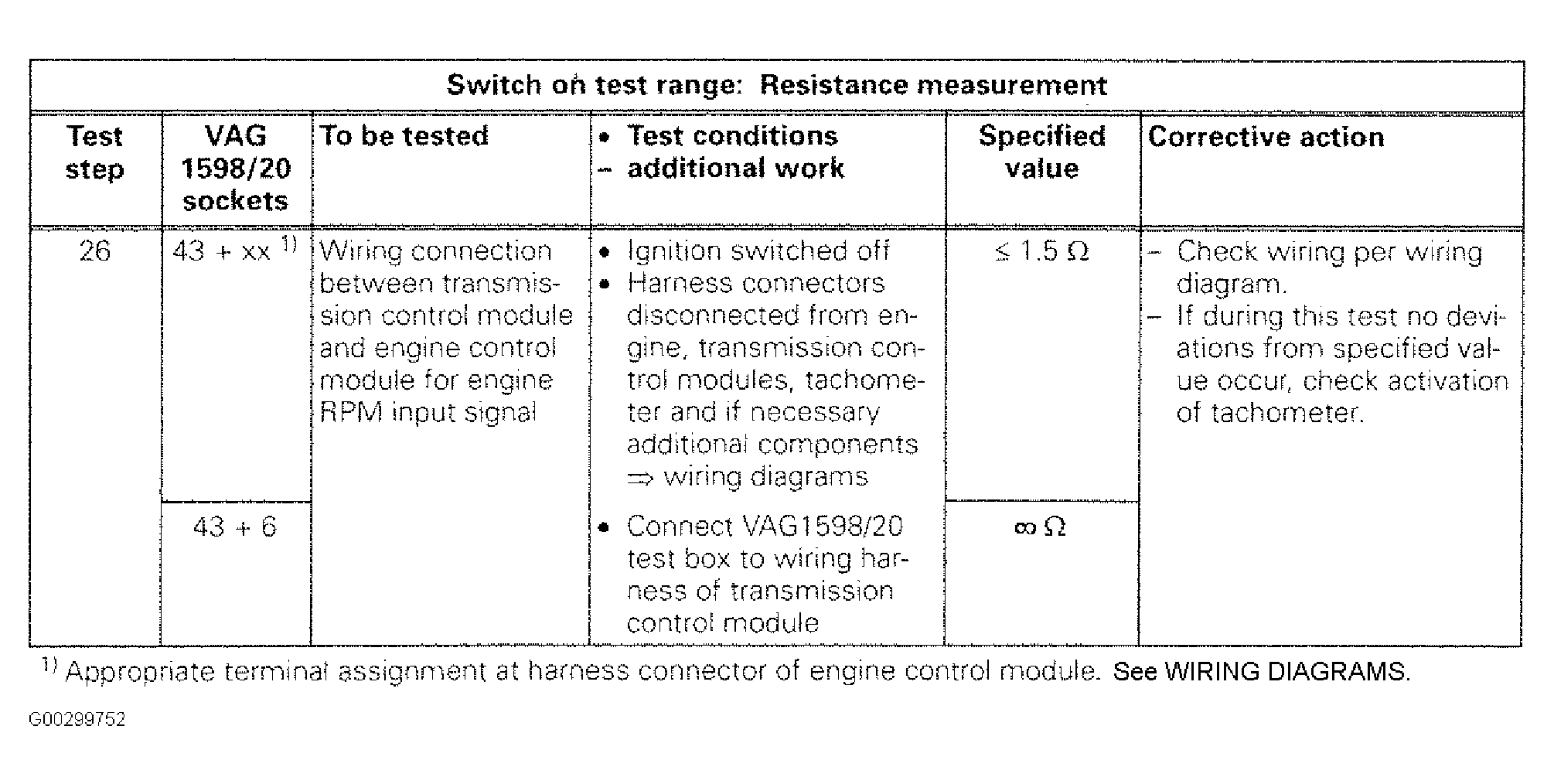
Carry out only appropriate test steps for components or wiring connections to be tested. See TRANSMISSION CONTROL TESTS (1996)
table. Given specified values are valid for an ambient temperature of 32-104°F (0-40°C). If values deviate from specified values, determine malfunction per wiring diagram. See WIRING DIAGRAMS
. If measured values deviate slightly from specified values, clean terminals and connections of test unit and adapters, repeat test. Before replacing respective component, check wires and connections, repeat resistance checks, especially on components with a specified values of less than 10,000 ohms.
TRANSMISSION CONTROL MODULE 88-PIN TERMINAL ASSIGNMENT
| TCM Connector Terminal No. |
Terminal Assignment |
| 1 |
Not Used |
| 2 |
Relay For Selector Lever Lock |
| 3 |
Not Used |
| 4 |
Not Used |
| 5 |
Solenoid Valve No. 4 (Pressure Regulator) |
| 6 |
Ground |
| 7 |
Accelerator Pedal Value From ECM (Throttle Body) |
| 8 |
Multi-Function Transmission Range Switch |
| 9 |
Not Used |
| 10 |
Shift Lock Solenoid/Brake Light Switch |
| 11 |
Not Used |
| 12 |
Not Used |
| 13 |
Not Used |
| 14 |
Transmission Vehicle Speed Sensor |
| 15 |
Transmission Vehicle Speed Sensor Shielding |
| 16 |
Not Used |
| 17 |
MIL Signal To ECM |
| 18 |
Kick Down Signal |
| 19 |
Input Signal From ABS Control Module |
| 20 |
Ignition Timing Angle Retarding/Injection Amount Decrease |
| 21 |
Transmission Fluid Temperature Sensor |
| 22 |
Transmission Fluid Temperature Sensor |
| 23 |
Not Used |
| 24 |
Output Signal For Cruise Control |
| 25 |
Transmission Range Selector Lever Display |
| 26 |
Supply Voltage (Terminal No. 30) |
| 27 |
Shut Off A/C At Kick Down |
| 28 |
Not Used |
| 29 |
Not Used |
| 30 |
Solenoid Valve No. 1 |
| 31 |
K-Wire For Diagnostics |
| 32 |
Solenoid Valve No. 3 |
| 33 |
Solenoid Valve No. 2 |
| 34 |
Not Used |
| 35 |
Fuel Consumption Signal |
| 36 |
Multi-Function Transmission Range Switch |
| 37 |
Multi-Function Transmission Range Switch |
| 38 |
Left Front ABS Wheel Speed Sensor |
| 39 |
Right Front ABS Wheel Speed Sensor |
| 40 |
Left Rear ABS Wheel Speed Sensor |
| 41 |
Right Rear ABS Wheel Speed Sensor |
| 42 |
Transmission Vehicle Speed Sensor |
| 43 |
Engine Speed Signal |
| 44 |
Not Used |
| 45 |
Not Used |
| 46 |
Not Used |
| 47 |
Not Used |
| 48 |
Not Used |
| 49 |
Not Used |
| 50 |
Supply Voltage (Cruise Control Only) |
| 51 |
Not Used |
| 52 |
Not Used |
| 53 |
Supply Voltage For Solenoid Valves |
| 54 |
Not Used |
| 55 |
Supply Voltage (Terminal No. 15) |
| 56 |
Not Used |
| 57 |
Not Used |
| 58 |
Not Used |
| 59 |
Not Used |
| 60 |
Not Used |
| 61 |
Not Used |
| 62 |
Not Used |
| 63 |
Not Used |
| 64 |
Not Used |
| 65 |
Not Used |
| 66 |
Not Used |
| 67 |
Not Used |
| 68 |
Not Used |
| 69 |
Not Used |
| 70 |
Not Used |
| 71 |
Not Used |
| 72 |
Not Used |
| 73 |
Not Used |
| 74 |
Not Used |
| 75 |
Not Used |
| 76 |
Not Used |
| 77 |
Not Used |
| 78 |
Not Used |
| 79 |
Not Used |
| 80 |
Not Used |
| 81 |
Not Used |
| 82 |
Not Used |
| 83 |
Not Used |
| 84 |
Not Used |
| 85 |
Not Used |
| 86 |
Not Used |
| 87 |
Not Used |
| 88 |
Not Used |
TRANSMISSION CONTROL TESTS (1996)
| Component To Be Tested |
Test Step |
| Supply Voltage From TCM |
1, 2 & 3. See Fig 1 |
| Shift Lock Solenoid |
27. See Figure
and Fig 21 |
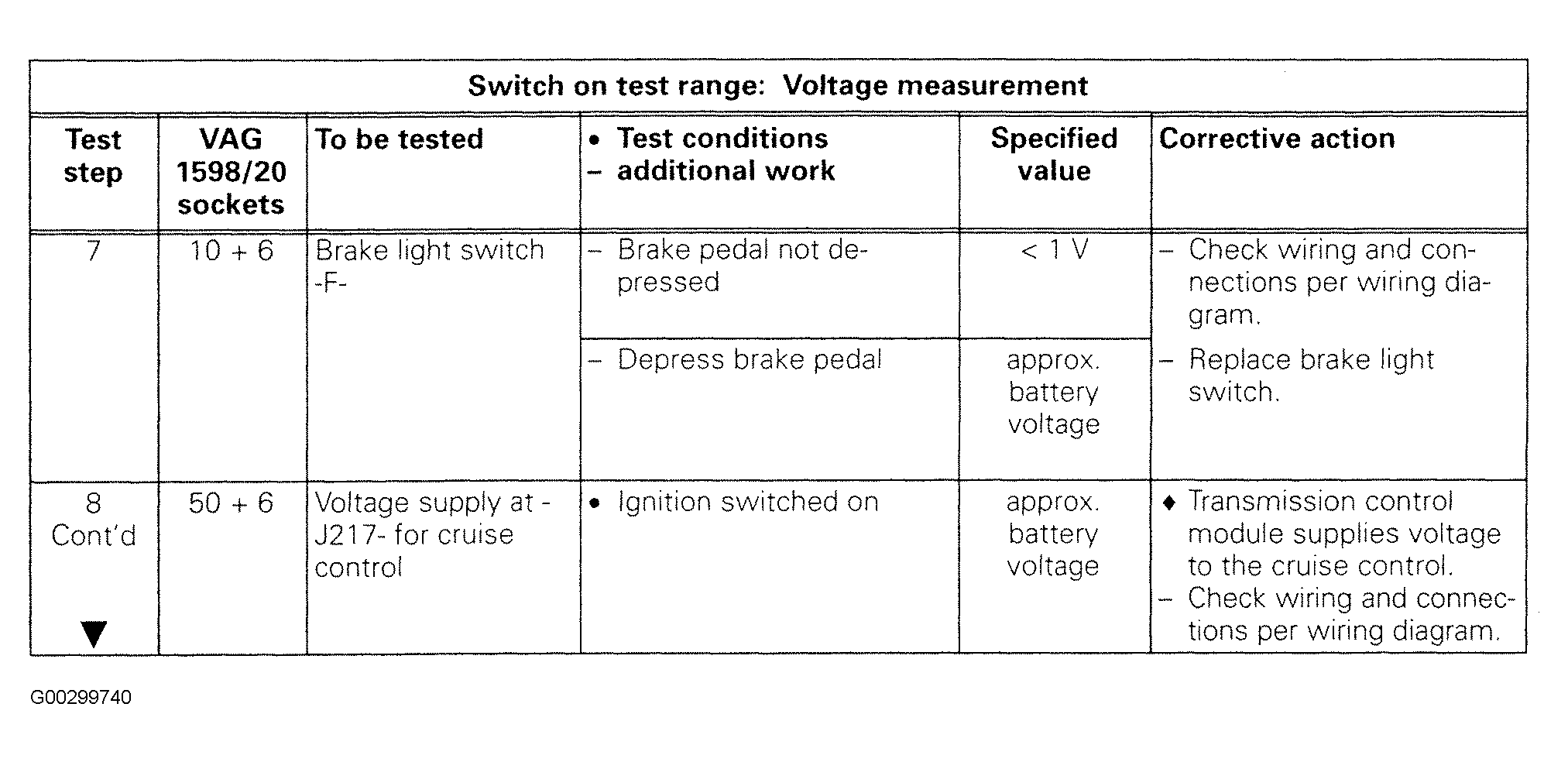
| Brake Light Switch |
7. See Fig 8 |
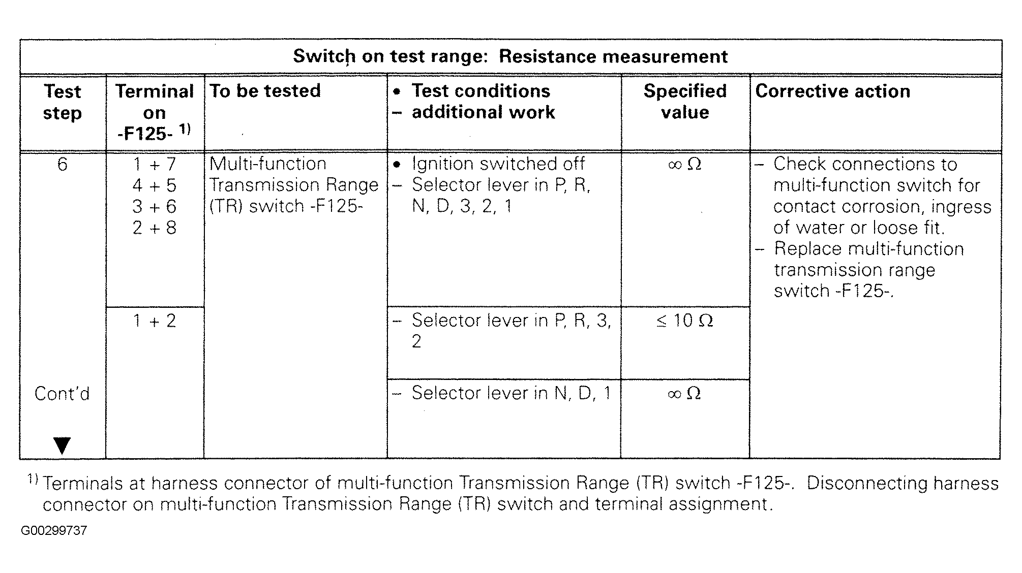
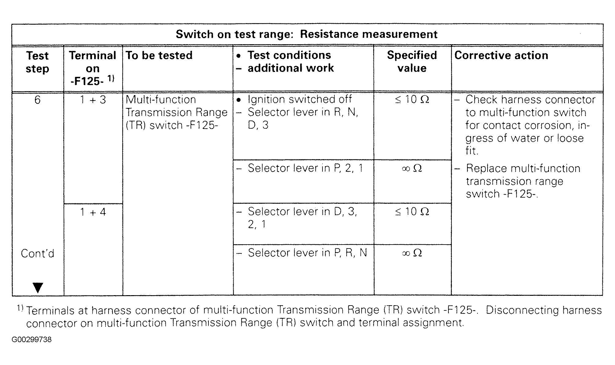
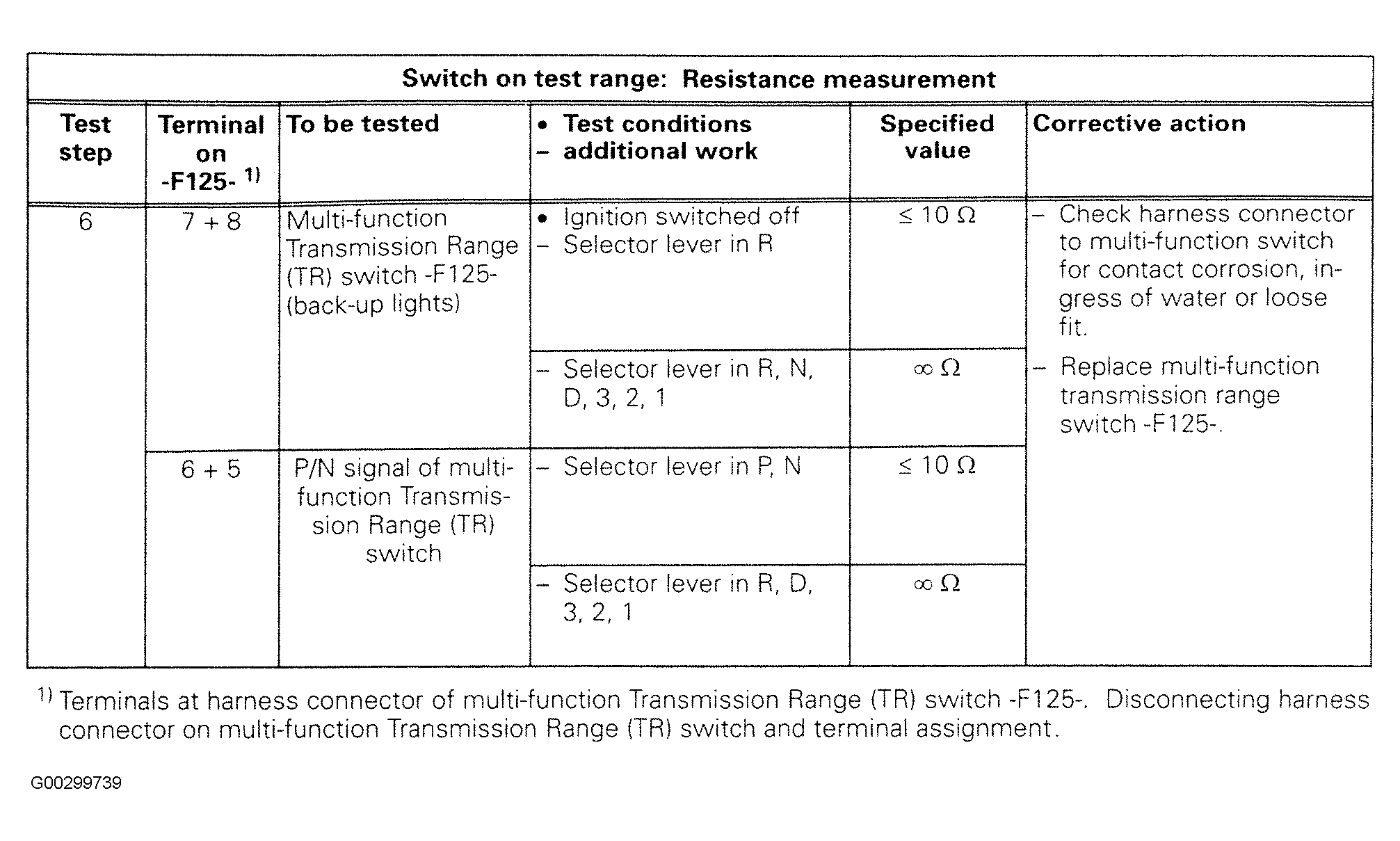
| Multi-Function Transmission Range Switch |
4, 5 & 6. See Figure
and Fig 2
-Fig 7 |
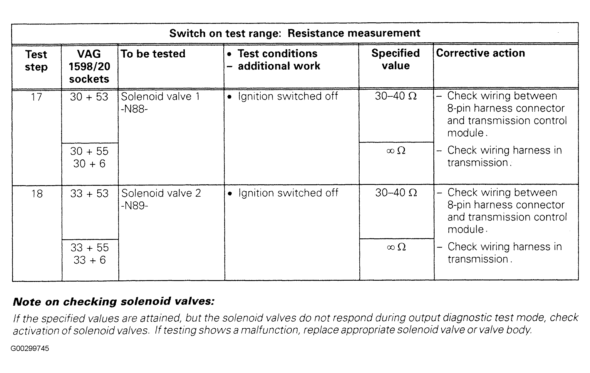
| Solenoid Valve No. 1 |
17. See Fig 13 |
| Solenoid Valve No. 2 |
18. See Fig 13 |
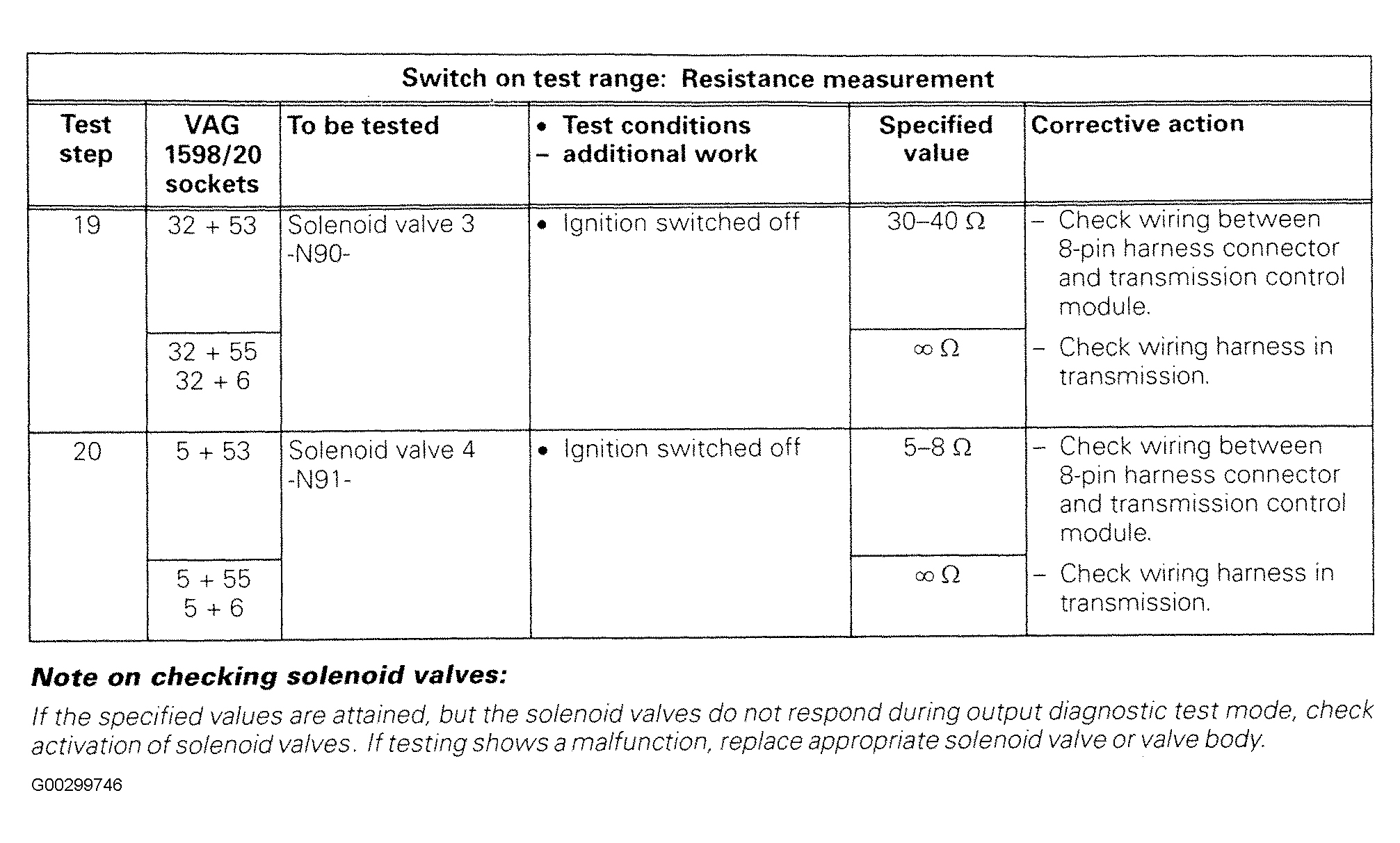
| Solenoid Valve No. 3 |
19. See Fig 14 |
| Solenoid Valve No. 4 |
20. See Fig 14 |
| Fuel Consumption Signal |
24. See Fig 17
and Fig 18 |
| Cruise Control |
8. See Figure
, Fig 8
and Fig 9 |
| Input Signal From ABS Control Module |
16. See Fig 11
and Fig 12 |
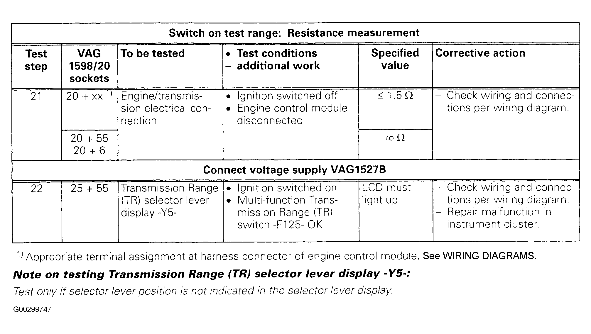
| Transmission Range Selector Lever Display |
22. See Fig 15 |
| Engine Speed (RPM) |
25 & 26. See Fig 19
and Fig 20 |
| Kick Down Switch |
9 & 28. See Fig 10
and Fig 22 |
| Transmission Vehicle Speed Sensor |
11. See Fig 10 |
| Wheel Speed Sensors |
12, 13, 14 & 15. See Fig 11
and Fig 12 |
| Transmission Fluid Temperature Sensor |
10. See Fig 10 |
| Engine/Transmission Electrical Connection |
21. See Fig 15 |
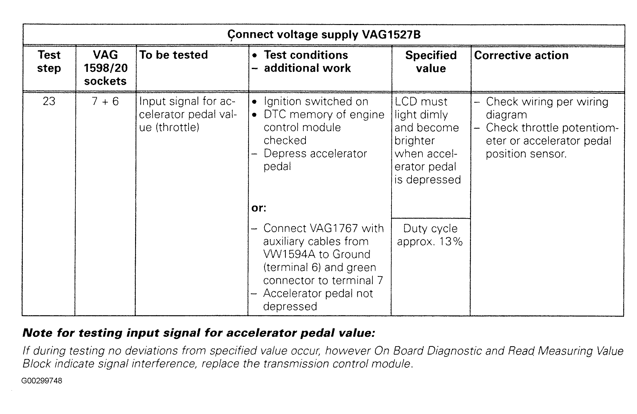
| Input Signal For Accelerator Pedal Value (Throttle) |
23. See Fig 16 |
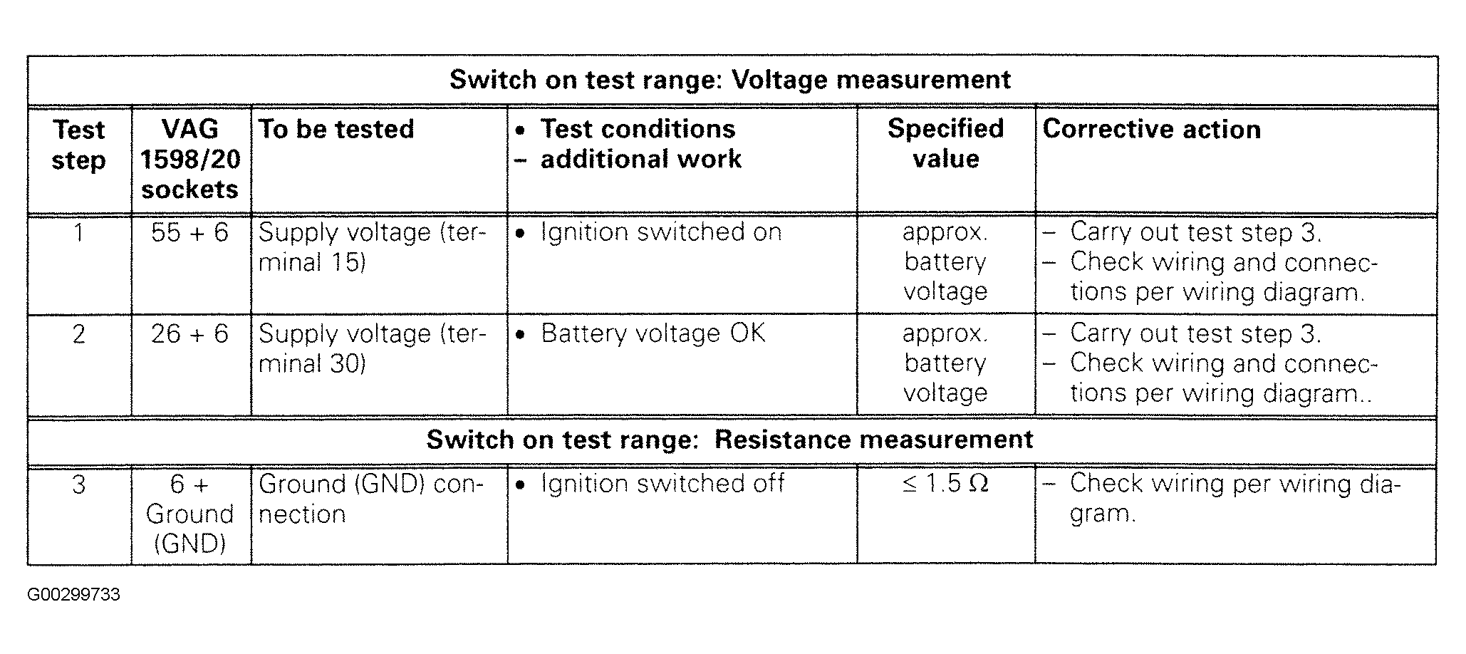 Courtesy of AUDI OF AMERICA, INC.
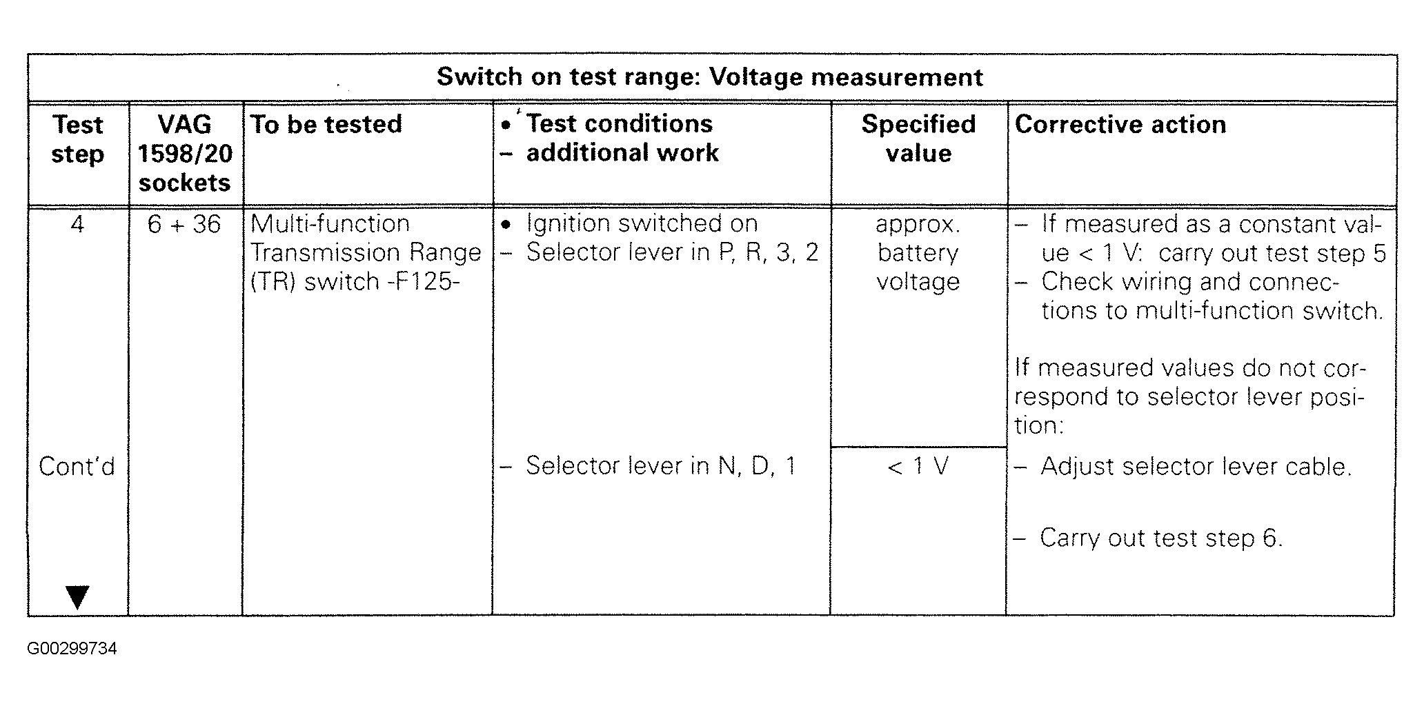 Courtesy of AUDI OF AMERICA, INC.
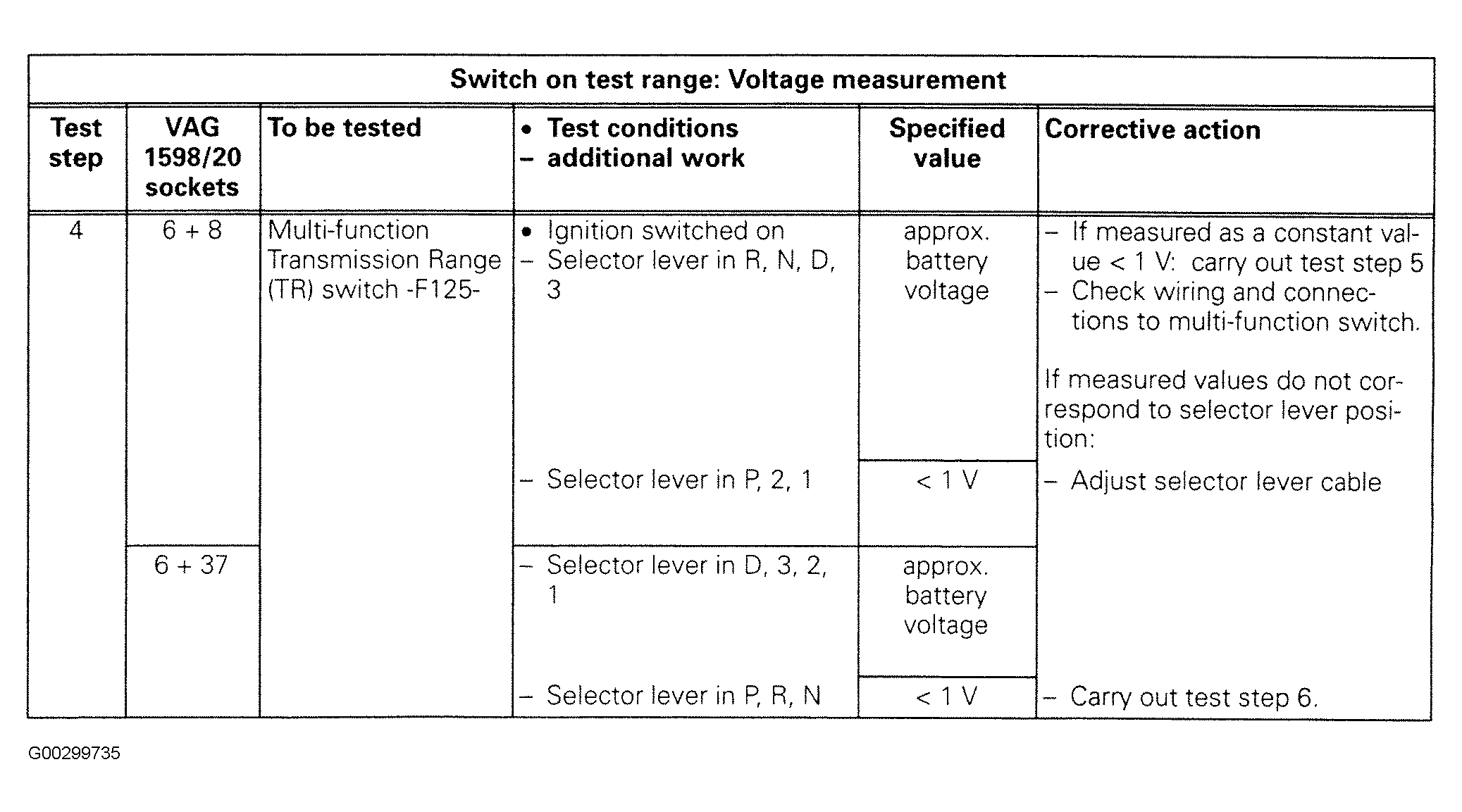 Courtesy of AUDI OF AMERICA, INC.
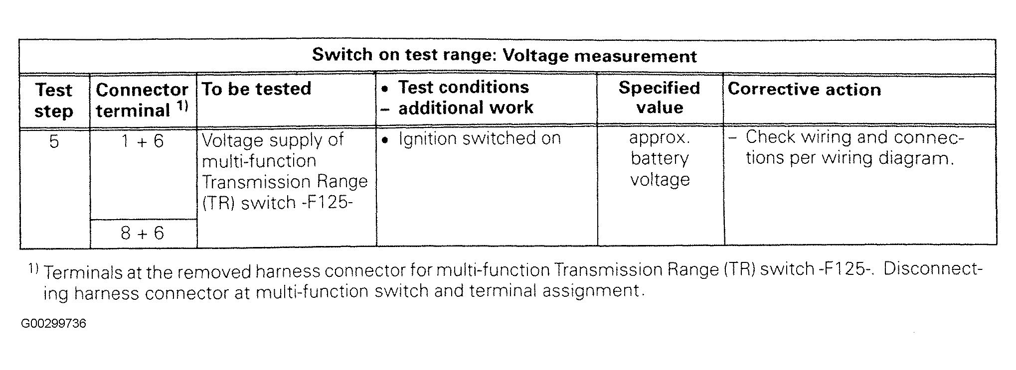 Courtesy of AUDI OF AMERICA, INC.
 Courtesy of AUDI OF AMERICA, INC.
 Courtesy of AUDI OF AMERICA, INC.
 Courtesy of AUDI OF AMERICA, INC.
 Courtesy of AUDI OF AMERICA, INC.
 Courtesy of AUDI OF AMERICA, INC.
 Courtesy of AUDI OF AMERICA, INC.
 Courtesy of AUDI OF AMERICA, INC.
 Courtesy of AUDI OF AMERICA, INC.
 Courtesy of AUDI OF AMERICA, INC.
 Courtesy of AUDI OF AMERICA, INC.
 Courtesy of AUDI OF AMERICA, INC.
 Courtesy of AUDI OF AMERICA, INC.
 Courtesy of AUDI OF AMERICA, INC.
 Courtesy of AUDI OF AMERICA, INC.
 Courtesy of AUDI OF AMERICA, INC.
 Courtesy of AUDI OF AMERICA, INC.
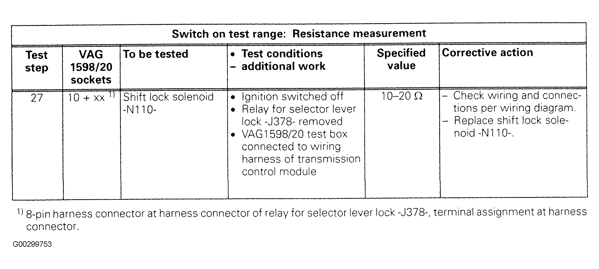 Courtesy of AUDI OF AMERICA, INC.
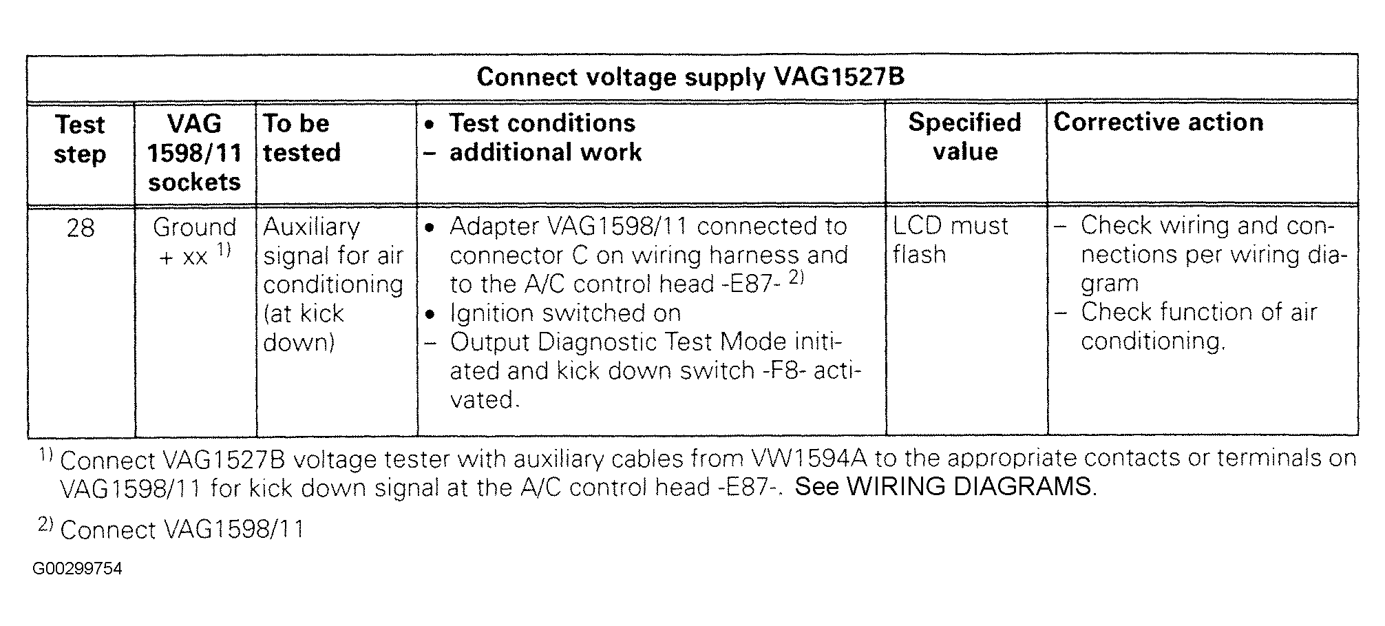 Courtesy of AUDI OF AMERICA, INC.