Audio-Navigation Unit Connector for Inputs and Outputs (2013-15)
WARNING: This page is about a different car, the 2016 Acura RDX, 2015 Acura RDX, 2014 Acura RDX, and 2013 Acura RDX. However, it is still accessible from the selected car via links, so may be relevant.
Audio-Navigation Unit Connector for Inputs and Outputs
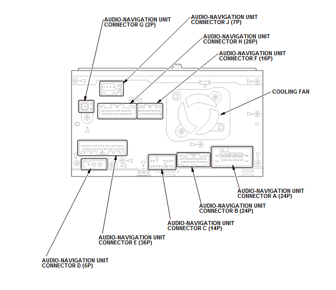 Courtesy of HONDA, U.S.A., INC. Courtesy of HONDA, U.S.A., INC.
|
AUDIO-NAVIGATION UNIT CONNECTOR A (24P)
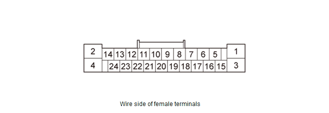 Courtesy of HONDA, U.S.A., INC. Courtesy of HONDA, U.S.A., INC.
|
| Cavity |
Wire Color |
Terminal Name |
Description |
Voltage (about) |
Symptom |
| A1 |
BLK |
GND |
Ground for audio-navigation unit (G504) |
0 V |
If open: Navigation screen goes black (backlight still operates). Audio system does not work.If short to ground: No effect on system. |
| A2 |
YEL |
ILL- (LED) |
Detects illumination control signal |
Lights on:0 V - battery voltage (depends on dash brightness) |
If open/short: When brightness=Auto, night mode for the display is inoperative when lights on. Diagnostic screen Car Status, ILL CANCEL = 0. |
| A3 |
GRN |
+B BACK UP |
Continuous power source |
Battery voltage |
If open: Navigation screen goes black (backlight still operates). Audio system does not work.If short to ground: Blows the No. A29 (10 A) fuse in the under-hood fuse/relay box. |
| A4 |
GRY |
ILLUMI+ |
Detects parking light on signal |
Lights on:battery voltage, Lights off: 0 V |
If open: When brightness=Auto, night mode for the display is inoperative when lights on. Diagnostic screen Car Status, ILL = 0.If short to ground: Blows the No. B35 (7.5 A) fuse in the under-dash fuse/relay box. |
| A5 |
YEL |
RL PRE+ (ELS) |
Outputs sound signal for left rear channel |
- - - |
- - - |
| A6 |
PUR |
RL PRE- (ELS) |
Outputs sound signal for left rear channel |
- - - |
- - - |
| A7 |
GRY |
SH RR PRE (ELS) |
Shield for terminals No. 5 and No. 6 |
- - - |
- - - |
| A8 |
Not used |
Not used |
- - - |
- - - |
- - - |
| A9 |
ORN |
RR PRE + (ELS) |
Outputs sound signal for Right rear channel |
- - - |
- - - |
| A10 |
BLU |
RR PRE- (ELS) |
Outputs sound signal for Right rear channel |
- - - |
- - - |
| A11 |
BRN |
REMOTE SW GND |
Audio remote-HFL switch ground |
0 V |
- - - |
| A12 |
BRN |
SCTY RADIO SW2 |
Security signal from MICU |
- - - |
If open: The security system sets. |
| A13 |
LT BLU |
K LINE |
Detects scan tool signal (serial data) |
- - - |
- - - |
| A14 |
Not used |
Not used |
- - - |
- - - |
- - - |
| A15 |
WHT |
FL PRE+ (ELS) |
Outputs sound signal for left front channel |
- - - |
- - - |
| Cavity |
Wire Color |
Terminal Name |
Description |
Voltage (about) |
Symptom |
| A16 |
BLK |
FL PRE- (ELS) |
Outputs sound signal for left front channel |
- - - |
- - - |
| A17 |
GRY |
SH FR PRE (ELS) |
Shield for terminals No. 15 and No. 16 |
- - - |
- - - |
| A18 |
Not used |
Not used |
- - - |
- - - |
- - - |
| A19 |
RED |
FR PRE+ (ELS) |
Outputs sound signal for right front speakers |
- - - |
- - - |
| A20 |
GRN |
FR PRE- (ELS) |
Outputs sound signal for right front speakers |
- - - |
- - - |
| A21 |
YEL |
SWD +B |
Outputs signal for stereo amplifier switching on/off |
Vehicle is in ACC mode: 10.5 V |
- - - |
| A22 |
PNK |
AUDIO REMOTE SW |
Detects control signal from audio remote switch |
- - - |
- - - |
| A23 |
BLU |
VSP |
Detects vehicle speed pulse from PCM |
Vehicle is in ACC mode: 5 V Vehicle is in ON mode: Pulses (depends on vehicle speed) |
If open/short: No vehicle speed pulse. Diagnostic screen Car Status, VSP = 0. |
| A24 |
PUR |
ACC |
Power source for accessories |
Vehicle is in ACC mode: Battery voltage |
If open: Navigation screen goes black (backlight still operates). Audio system does not work.If short to ground: Blows the No. B19 (7.5 A) fuse in the under-dash fuse/relay box. |
AUDIO-NAVIGATION UNIT CONNECTOR B (24P)
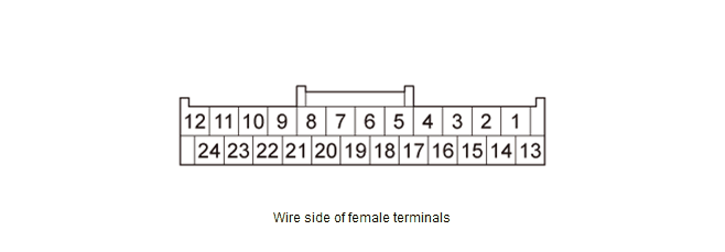 Courtesy of HONDA, U.S.A., INC. Courtesy of HONDA, U.S.A., INC.
|
| Cavity |
Wire Color |
Terminal Name |
Description |
Voltage (about) |
Symptom |
| B1 |
PNK |
SUB W PRE+ (ELS) |
Outputs sound signal for subwoofer channel |
- - - |
- - - |
| B2 |
GRY |
SH CTR SUB W PRE (ELS) |
Shield for terminals No. 1, No. 3, No. 4, and No. 13 |
- - - |
- - - |
| B3 |
LT GRN |
CTR PRE+ (ELS) |
Outputs sound signal for center channel |
- - - |
- - - |
| B4 |
BRN |
CTR PRE- (ELS) |
Outputs sound signal for center channel |
- - - |
- - - |
| B5 |
Not used |
Not used |
- - - |
- - - |
- - - |
| B6 |
Not used |
Not used |
- - - |
- - - |
- - - |
| B7 |
Not used |
Not used |
- - - |
- - - |
- - - |
| B8 |
GRN |
TELEM SIG + |
Inputs HFL prompts and telephone sound signal from HandsFreeLink control unit |
- - - |
- - - |
| B9 |
Not used |
Not used |
- - - |
- - - |
- - - |
| B10 |
PUR |
AUX DET |
Detects connection signal for auxiliary jack assembly |
- - - |
- - - |
| B11 |
PNK |
AUX SGND |
Ground for sound signal from auxiliary jack assembly |
- - - |
- - - |
| B12 |
BLU |
AUX L CH |
Inputs sound signal from auxiliary jack assembly |
- - - |
- - - |
| B13 |
LT BLU |
SUB W PRE - (ELS) |
Outputs sound signal for subwoofer channel |
- - - |
- - - |
| B14 |
Not used |
Not used |
- - - |
- - - |
- - - |
| B15 |
BLU |
NAVI GND |
Ground for voice guidance and Voice Recognition (VR) prompts |
0 V |
If open: If navi voice activated, speakers buzz; if voice off, no effect.If short to ground: No effect on voice output. |
| B16 |
GRY |
NAVI CH SH |
Shield for terminals No. 15 and No. 17 |
0 V |
If open/short to ground: No effect on voice output. |
| Cavity |
Wire Color |
Terminal Name |
Description |
Voltage (about) |
Symptom |
| B17 |
PNK |
NAVI LCH |
Outputs front audio signal of voice guidance and Voice Recognition (VR) prompts |
Audio signal0.004 - 0.04 V (depends on navi voice out) |
If open/short: If navi voice activated, speakers buzz; if voice off, no effect. |
| B18 |
Not used |
Not used |
- - - |
- - - |
- - - |
| B19 |
Not used |
Not used |
- - - |
- - - |
- - - |
| B20 |
GRY |
SH TELEM SIG |
Shield for terminals No. 8 and No. 21 |
- - - |
- - - |
| B21 |
RED |
TELEM SIG - |
Inputs HFL prompts and telephone sound signal from HandsFreeLink control unit |
- - - |
- - - |
| B22 |
GRY |
SH AUX |
Shield for terminals No. 11, No. 12, and No. 24 |
- - - |
- - - |
| B23 |
YEL |
AUX GND |
Ground for auxiliary jack assembly |
- - - |
- - - |
| B24 |
GRN |
AUX R CH |
Inputs sound signal from auxiliary jack assembly |
- - - |
- - - |
AUDIO-NAVIGATION UNIT CONNECTOR C (14P)
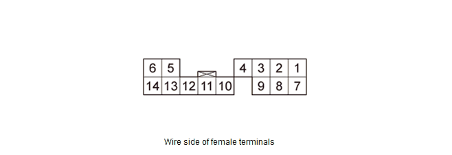 Courtesy of HONDA, U.S.A., INC. Courtesy of HONDA, U.S.A., INC.
|
| Cavity |
Wire Color |
Terminal Name |
Description |
Voltage (about) |
Symptom |
| C1 |
BLK |
GA AUDIO L+ |
Inputs sound signal from GA-Net related units |
- - - |
- - - |
| Cavity |
Wire Color |
Terminal Name |
Description |
Voltage (about) |
Symptom |
| C2 |
RED |
GA AUDIO R+ |
Inputs sound signal from GA-Net related units |
- - - |
- - - |
| C3 |
GRY |
SH GA AUDIO |
Shield for terminals No. 1, No. 2, No. 7, and No. 8 |
- - - |
- - - |
| C4 |
GRY |
SH GA BUS |
Shield for terminals No. 11 and No. 12 |
0 V |
If open/short to ground: No effect on system. |
| C5 |
YEL |
GA SYS ON |
Output signal for GA-Net related units switching on/off |
Vehicle is in ACC mode: 0 VVehicle is in OFF mode: Battery voltage |
If open: System Link screen XM and HFL icon shows red.If short to ground: No effect on system. |
| C6 |
RED |
GA +B |
Outputs power source for GA-Net related units |
Battery voltage |
If open/short: System Link screen XM and HFL icon shows red. |
| C7 |
GRN |
GA AUDIO L - |
Inputs sound signal from GA-Net related units |
- - - |
- - - |
| C8 |
WHT |
GA AUDIO R - |
Inputs sound signal from GA-Net related units |
- - - |
- - - |
| C9 |
Not used |
Not used |
- - - |
- - - |
- - - |
| C10 |
BRN |
GA GND |
GA-Net related units ground |
0 V |
If open: System Link screen XM and HFL icon shows red.If short to ground: No effect on system. |
| C11 |
PUR |
GA BUS - |
GA-Net bus communication signal |
Vehicle is in ACC mode: Pulses (depends on bus traffic) |
If open/short: Navigation screen goes black (backlight still operates). |
| C12 |
LT BLU |
GA BUS + |
GA-Net bus communication signal |
Vehicle is in ACC mode: Pulses (depends on bus traffic) |
If open/short: Navigation screen goes black (backlight still operates). |
| C13 |
Not used |
Not used |
- - - |
- - - |
- - - |
| C14 |
Not used |
Not used |
- - - |
- - - |
- - - |
AUDIO-NAVIGATION UNIT CONNECTOR D (5P)
 Courtesy of HONDA, U.S.A., INC. Courtesy of HONDA, U.S.A., INC.
|
| Cavity |
Wire Color |
Terminal Name |
Description |
Voltage (about) |
Symptom |
| D1 |
- - - |
SWD +B |
Power source for AM/FM/XM antenna |
- - - |
- - - |
| D2 |
- - - |
AM/FM |
Inputs AM/FM signal |
- - - |
- - - |
| D3 |
Not used |
Not used |
- - - |
- - - |
- - - |
| D4 |
- - - |
SH (AM/FM) |
Shield for terminal No. 2 |
- - - |
- - - |
| D5 |
Not used |
Not used |
- - - |
- - - |
- - - |
AUDIO-NAVIGATION UNIT CONNECTOR E (36P)
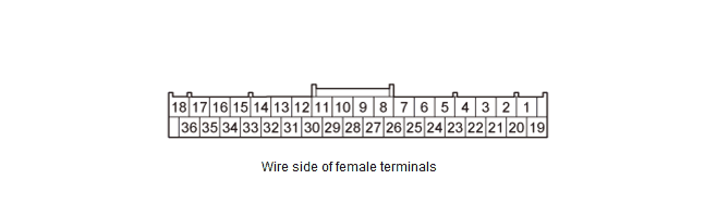 Courtesy of HONDA, U.S.A., INC. Courtesy of HONDA, U.S.A., INC.
|
| Cavity |
Wire Color |
Terminal Name |
Description |
Voltage (about) |
Symptom |
| E1 |
Not used |
Not used |
- - - |
- - - |
- - - |
| E2 |
Not used |
Not used |
- - - |
- - - |
- - - |
| E3 |
Not used |
Not used |
- - - |
- - - |
- - - |
| E4 |
LT GRN |
CAMERA BIT0 |
Mode select signal for rearview camera |
0 - 7 V (depends on rearview mode) |
If open/short: No change to rearview camera image. |
| E5 |
GRN |
ANC CHK2 |
Outputs ANC test signal |
- - - |
- - - |
| E6 |
Not used |
Not used |
- - - |
- - - |
- - - |
| Cavity |
Wire Color |
Terminal Name |
Description |
Voltage (about) |
Symptom |
| E7 |
PNK |
B CAN-H |
Communication signal |
Vehicle is in ON mode: Pulses (depends on bus traffic) |
If open: System Link B-CAN icon shown as red.If short: Same diagnostic conditions as when open, and also sets the B-CAN DTC (B-CAN BUS OFF). |
| E8 |
Not used |
Not used |
- - - |
- - - |
- - - |
| E9 |
Not used |
Not used |
- - - |
- - - |
- - - |
| E10 |
Not used |
Not used |
- - - |
- - - |
- - - |
| E11 |
GRN |
AMP DATA + |
Communication signal to stereo amplifier |
- - - |
- - - |
| E12 |
RED |
AMP DATA - |
Communication signal to stereo amplifier |
- - - |
- - - |
| E13 |
GRY |
SH VOL ENC |
Shield for terminals No. 14, No. 31, and No. 32 |
- - - |
- - - |
| E14 |
GRN |
VOL ENC - |
Inputs volume encoder signal |
- - - |
- - - |
| E15 |
GRY |
SH OPERA |
Shield for terminals No. 16 and No. 34 |
- - - |
- - - |
| E16 |
YEL |
OPERA RX |
Communication signal for audio-navigation switch panel buttons |
- - - |
- - - |
| E17 |
GRY |
SH DUET |
Shield for terminals No. 18 and No. 36 |
- - - |
- - - |
| E18 |
RED |
DUET RX |
Communication signal for audio-navigation switch panel display |
- - - |
- - - |
| E19 |
Not used |
Not used |
- - - |
- - - |
- - - |
| E20 |
Not used |
Not used |
- - - |
- - - |
- - - |
| E21 |
Not used |
Not used |
- - - |
- - - |
- - - |
| E22 |
Not used |
Not used |
- - - |
- - - |
- - - |
| E23 |
YEL |
CAMERA BIT1 |
Mode select signal for rearview camera |
0 - 7 V (depends on rearview mode) |
If open/short: No change to rearview camera image. |
| E24 |
Not used |
Not used |
- - - |
- - - |
- - - |
| E25 |
Not used |
Not used |
- - - |
- - - |
- - - |
| Cavity |
Wire Color |
Terminal Name |
Description |
Voltage (about) |
Symptom |
| E26 |
Not used |
Not used |
- - - |
- - - |
- - - |
| E27 |
BLU |
B CAN-L |
Communication signal |
Vehicle is in ON mode: Pulses (depends on bus traffic) |
If open: System Link B-CAN icon shown as red.If short: Same diagnostic conditions as when open, and also sets the B-CAN DTC (B-CAN BUS OFF). |
| E28 |
Not used |
Not used |
- - - |
- - - |
- - - |
| E29 |
Not used |
Not used |
- - - |
- - - |
- - - |
| E30 |
GRY |
SH AMP DATA |
Shield for terminals No. 11 and No. 12 |
- - - |
- - - |
| E31 |
PNK |
PWR SW |
Inputs POWER switch on/off signal |
- - - |
- - - |
| E32 |
BLU |
VOL ENC + |
Inputs volume encoder signal |
- - - |
- - - |
| E33 |
GRN |
OPERA CONT |
OPERA control signal |
- - - |
- - - |
| E34 |
BRN |
OPERA TX |
Communication signal for audio-navigation switch panel buttons |
- - - |
- - - |
| E35 |
LT BLU |
DUET CONT |
DUET control signal |
- - - |
- - - |
| E36 |
GRN |
DUET TX |
Communication signal for audio-navigation switch panel display |
- - - |
- - - |
AUDIO-NAVIGATION UNIT CONNECTOR F (16P)
 Courtesy of HONDA, U.S.A., INC. Courtesy of HONDA, U.S.A., INC.
|
| Cavity |
Wire Color |
Terminal Name |
Description |
Voltage (about) |
Symptom |
| F1 |
WHT |
DISPLAY R |
Outputs red color signal |
0.7 V AC average in RGB color diagnostic mode |
If open: Red color missing (see RGB Color diagnosis).If short: Symptom same as open, or navigation screen goes black (backlight still operates). |
| F2 |
RED |
DISPLAY G |
Outputs green color signal |
0.7 V AC average in RGB color diagnostic mode |
If open: Green color missing (see RGB Color diagnosis).If short: Symptom same as open, or navigation screen goes black (backlight still operates). |
| F3 |
YEL |
DISPLAY B |
Outputs blue color signal |
0.7 V AC average in RGB color diagnostic mode |
If open: Blue color missing (see RGB Color diagnosis).If short: Symptom same as open, or navigation screen goes black (backlight still operates). |
| F4 |
BLK |
DISPLAY RGB GND |
Ground for color signals |
0 V |
If open/short: No effect on system. |
| F5 |
GRY |
SYSTEM GND |
Ground for Composite signal |
0 V |
If open/short to ground: No effect on system. |
| F6 |
Not used |
Not used |
- - - |
- - - |
- - - |
| F7 |
Not used |
Not used |
- - - |
- - - |
- - - |
| F8 |
Not used |
Not used |
- - - |
- - - |
- - - |
| F9 |
BRN |
DISPLAY VBS |
Composite video(vertical/horizontal)synchronizing signal |
0.3 V AC average in RGB color diagnostic mode |
If open: Picture rolls horizontally, colors still visible.If short: Symptom same as open, or navigation screen goes black (backlight still operates). |
| F10 |
GRN |
DISPLAY YS |
Overlay control signal |
1.0 V AC average (depends on display mode) |
If open/short: Rearview camera guide line does not display. |
| F11 |
BLU |
DISPLAY SYNC GND |
Ground for synchronizingsignal |
0 V |
If open/short: No effect on system. |
| F12 |
GRY |
SH DISPLAY RGB |
Shield for terminals No. 1, No. 2, No. 3, No. 4, No. 9, No. 10, and No. 11 |
0 V |
If open/short to ground: No effect on system. |
| F13 |
Not used |
Not used |
- - - |
- - - |
- - - |
| F14 |
PNK |
DISP GND |
Ground for Composite signal |
0 V |
If open: No effect on system. |
| F15 |
GRY |
BACK LT |
Reverse signal ofselect lever fromreverse relay circuit |
In R: battery voltageOtherwise: 0 V |
If open/short: When shift lever is in R, diagnostic screen Car Status, BACK = 0. |
| F16 |
Not used |
Not used |
- - - |
- - - |
- - - |
AUDIO-NAVIGATION UNIT CONNECTOR G (2P)
 Courtesy of HONDA, U.S.A., INC. Courtesy of HONDA, U.S.A., INC.
|
| Cavity |
Wire Color |
Terminal Name |
Description |
Voltage (about) |
Symptom |
| G1 |
- - - |
GPS SIG |
Inputs GPS signal |
Vehicle is in ACC mode: 5 V |
If open/short to ground: GPS icon on screen is not shown, System Link screen GPS Ant. shows red. |
| G2 |
- - - |
SH GPS SIG |
Shield for terminal No. 1 |
- - - |
If open/short to ground: GPS icon on screen is not shown, System Link screen GPS Ant. shows red. |
AUDIO-NAVIGATION UNIT CONNECTOR H (28P)
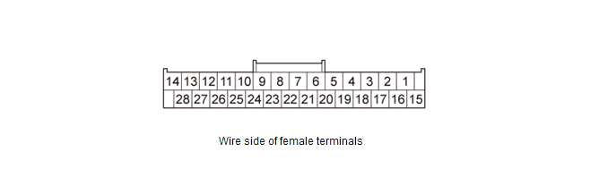 Courtesy of HONDA, U.S.A., INC. Courtesy of HONDA, U.S.A., INC.
|
| Cavity |
Wire Color |
Terminal Name |
Description |
Voltage (about) |
Symptom |
| H1 |
GRY |
SH HFT-NAVI MIC |
Shield for terminals No. 15 and No. 16 |
0 V |
If open/short to ground: No effect on system. |
| H2 |
GRY |
SH JOG |
Shield for terminal No. 17 |
0 V |
If open/short to ground: No effect on system. |
| H3 |
WHT |
F CAN-H |
Communication signal |
Vehicle is in ON mode: Pulses (depends on bus traffic) |
If open: System Link F-CAN icon shown as red.If short: Same diagnostic conditions as when open, and also sets the F-CAN DTC (F-CAN BUS OFF). |
| H4 |
Not used |
Not used |
- - - |
- - - |
- - - |
| Cavity |
Wire Color |
Terminal Name |
Description |
Voltage (about) |
Symptom |
| H5* |
RED |
HIP-NAVI COMM2 |
Communication signal to AcuraLink control unit (XM receiver) |
- - - |
If open/short: AcuraLink services do not work. System Link XM (HIP) icon shown as red. |
| H6* |
BLK |
HIP-NAVI COMM4 |
Communication signal to AcuraLink control unit (XM receiver) |
- - - |
If open/short: AcuraLink services do not work. System Link XM (HIP) icon shown as red. |
| H7 |
Not used |
Not used |
- - - |
- - - |
- - - |
| H8 |
Not used |
Not used |
- - - |
- - - |
- - - |
| H9 |
Not used |
Not used |
- - - |
- - - |
- - - |
| H10 |
LT GRN |
DIAG - |
Detects service check signal |
0 V |
If open: The system will not go into diagnostic mode when using the SCS service connector.If short to ground: No effect on system. |
| H11 |
Not used |
Not used |
- - - |
- - - |
- - - |
| H12 |
Not used |
Not used |
- - - |
- - - |
- - - |
| H13 |
Not used |
Not used |
- - - |
- - - |
- - - |
| H14 |
Not used |
Not used |
- - - |
- - - |
- - - |
| H15 |
BLU |
HFT-NAVI MIC+ |
Inputs Voice Recognition (VR) prompts from microphone via HandsFreeLink control unit |
Vehicle is in ACC mode: 8 V |
If open/short: You cannot operate voice control. System Link screen Mic icon shows red. |
| H16 |
PNK |
HFT-NAVI MIC- |
Inputs Voice Recognition (VR) prompts from microphone via HandsFreeLink control unit |
0 V |
If open/short: You cannot operate voice control. |
| H17 |
WHT |
JOG |
Communication signal for interface dial |
Vehicle is in ACC mode: 0 - 5 V pulses |
If open/short: You cannot operate navigation system. |
| H18 |
RED |
F CAN-L |
Communication signal |
Vehicle is in ON mode: Pulses (depends on bus traffic) |
If open: System Link F-CAN icon shown as red.If short: Same diagnostic conditions as when open, and also sets the F-CAN DTC (F-CAN BUS OFF). |
| H19* |
GRY |
SH HIP-NAVI COMM |
Shield for terminals No. 5, No. 6, No. 20, and No. 21 |
- - - |
If open/short to ground: No effect on system. |
| Cavity |
Wire Color |
Terminal Name |
Description |
Voltage (about) |
Symptom |
| H20* |
WHT |
HIP-NAVI COMM1 |
Communication signal to AcuraLink control unit (XM receiver) |
- - - |
If open/short: AcuraLink services do not work. System Link XM (HIP) icon shown as red. |
| H21* |
GRN |
HIP-NAVI COMM3 |
Communication signal to AcuraLink control unit (XM receiver) |
- - - |
If open/short: AcuraLink services do not work. System Link XM (HIP) icon shown as red. |
| H22 |
Not used |
Not used |
- - - |
- - - |
- - - |
| H23 |
Not used |
Not used |
- - - |
- - - |
- - - |
| H24 |
Not used |
Not used |
- - - |
- - - |
- - - |
| H25 |
RED |
DIAG + |
Detects service check signal |
5 - 6 V |
The system will not go into diagnostic mode when using the SCS service connector.If short to ground: System goes into System Link screen at ACC or ON mode. |
| H26 |
Not used |
Not used |
- - - |
- - - |
- - - |
| H27 |
Not used |
Not used |
- - - |
- - - |
- - - |
| H28 |
Not used |
Not used |
- - - |
- - - |
- - - |
AUDIO-NAVIGATION UNIT CONNECTOR J (7P)
 Courtesy of HONDA, U.S.A., INC. Courtesy of HONDA, U.S.A., INC.
|
| Cavity |
Wire Color |
Terminal Name |
Description |
Voltage (about) |
Symptom |
| J1 |
- - - |
USB GND |
Ground for communication signal |
0 V |
- - - |
| J2 |
- - - |
USB DATA + |
Communication signal |
- - - |
- - - |
| J3 |
- - - |
USB DATA - |
Communication signal |
- - - |
- - - |
| J4 |
- - - |
USB VBUS |
Outputs power source for USB device |
Vehicle is in ACC mode: 5 V |
- - - |
| Cavity |
Wire Color |
Terminal Name |
Description |
Voltage (about) |
Symptom |
| J5 |
- - - |
USB SH |
Shield for terminals No. 1, No. 2, No. 3, and No. 4 |
- - - |
- - - |
| J6 |
- - - |
USB DET |
Detects connection signal |
Connector J connected: 2 V or lessConnector J disconnected: Open |
If open: System Link USB icon shown as red.If short to ground: No effect on system. |
| J7 |
- - - |
USB DET GND |
Ground for connection signal |
0 V |
If open: System Link USB icon shown as red.If short to ground: No effect on system. |